|
|
|
PDF CL2 Data sheet ( Hoja de datos )
| Número de pieza | CL2 | |
| Descripción | Constant-Current LED Driver IC | |
| Fabricantes | Microchip | |
| Logotipo | ||
Hay una vista previa y un enlace de descarga de CL2 (archivo pdf) en la parte inferior de esta página. Total 15 Páginas | ||
|
No Preview Available !
CL2
Simple 90V, 20mA, Temperature Compensated,
Constant-Current LED Driver IC
Features
• 5.0 to 90V operating range (VA-B)
• 20 mA ±10% at 5.0 - 90V
• 0.01%/°C typical temperature coefficient
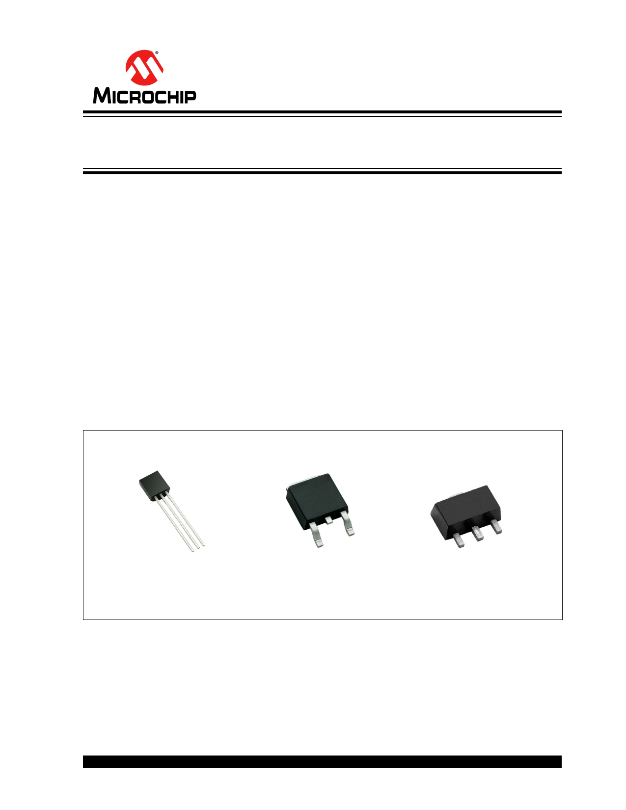
• Available in TO-243AA (SOT-89), TO-252(D-
PAK), & TO-92 packages
• Can be paralleled for higher current
Applications
• LED driver
• Industrial lamp indicators
• Signage
• Accent lighting
• Automotive
• Constant current source
• Constant current sink
Package Type
Description
CL2 is a high voltage, temperature compensated, con-
stant-current source. The device is trimmed to provide
a constant current of 20 mA ±10% at an input voltage
of 5–90V. The device can be used as a two-terminal,
constant-current source or constant-current sink.
A typical application for the CL2 is to drive LEDs with a
constant current of 20 mA. Multiple CL2s can also be
used in parallel to provide higher currents such as
40 mA, 60 mA or 80 mA. The device is available in TO-
243AA (SOT-89), TO-252 (D-PAK), and TO-92 pack-
ages.
VB
VA
TO-92
NC
See Table 2-1 for pin information
VB
N/C
VA
TO-252 (D-PAK)
VB
N/C
VB
VA
TO-243AA (SOT-89)
2015 Microchip Technology Inc.
DS20005448A-page 1
1 page 
CL2
3.0 FUNCTIONAL DESCRIPTION
Figure 3-1 provides the Functional Circuit diagram and
its equivalent block diagram for CL2. Performance
information is available in Figure 3-2 and Figure 3-3.
Figure 3-4 and Figure 3-5 provide example schemat-
ics.
VA VA
Control Circuit
and Temperature
Compensation
20mA
±10%
VB VB
Functional Circuit Diagram
Equivalent Block Diagram
FIGURE 3-1:
Functional Circuit Diagram and Equivalent Block Diagram
1.03
1.02
5.0V
45V
1.01
90V
1.00
0.99
0.98
-55 -35 -15
5 25 45 65 85 105 125 145
Temperature (°C)
FIGURE 3-2:
Temperature Characteristics
2015 Microchip Technology Inc.
DS20005448A-page 5
5 Page 
3-Lead TO-243AA (SOT-89) Package Outline (N8)
D
D1 C
EH
1
L
2
3
b
e
e1
Top View
b1
E1
A
Side View
CL2
Note: For the most current package drawings, see the Microchip Packaging Specification at www.microchip.com/packaging.
Symbol
A b b1 C
MIN 1.40 0.44 0.36 0.35
Dimensions
(mm)
NOM
-
-
-
-
MAX 1.60 0.56 0.48 0.44
JEDEC Registration TO-243, Variation AA, Issue C, July 1986.
† This dimension differs from the JEDEC drawing
Drawings not to scale.
D
4.40
-
4.60
D1
1.62
-
1.83
E
2.29
-
2.60
E1
2.00†
-
2.29
e
1.50
BSC
e1
3.00
BSC
H
3.94
-
4.25
L
0.73†
-
1.20
2015 Microchip Technology Inc.
DS20005448A-page 11
11 Page | ||
| Páginas | Total 15 Páginas | |
| PDF Descargar | [ Datasheet CL2.PDF ] | |
Hoja de datos destacado
| Número de pieza | Descripción | Fabricantes |
| CL-150 | ULTRA SMALL CHIP LEDS FOR USE IN VARIOUS ELECTRONIC PRODUCTS | ETC |
| CL-155 | ULTRA SMALL CHIP LEDS FOR USE IN VARIOUS ELECTRONIC PRODUCTS | ETC |
| CL-165 | ULTRA SMALL CHIP LEDS FOR USE IN VARIOUS ELECTRONIC PRODUCTS | ETC |
| CL-170 | ULTRA SMALL CHIP LEDS FOR USE IN VARIOUS ELECTRONIC PRODUCTS | ETC |
| Número de pieza | Descripción | Fabricantes |
| SLA6805M | High Voltage 3 phase Motor Driver IC. |
Sanken |
| SDC1742 | 12- and 14-Bit Hybrid Synchro / Resolver-to-Digital Converters. |
Analog Devices |
|
DataSheet.es es una pagina web que funciona como un repositorio de manuales o hoja de datos de muchos de los productos más populares, |
| DataSheet.es | 2020 | Privacy Policy | Contacto | Buscar |