|
|
|
PDF 841N254B Data sheet ( Hoja de datos )
| Número de pieza | 841N254B | |
| Descripción | NG Crystal-to-LVDS/ HCSL Clock Synthesizer | |
| Fabricantes | IDT | |
| Logotipo | ||
Hay una vista previa y un enlace de descarga de 841N254B (archivo pdf) en la parte inferior de esta página. Total 24 Páginas | ||
|
No Preview Available !
FemtoClock® NG Crystal-to-LVDS/ HCSL
Clock Synthesizer
841N254B
Datasheet
General Description
The 841N254B is a 4-output clock synthesizer designed for S-RIO
1.3 and 2.0 reference clock applications. The device generates four
copies of a selectable 250MHz, 156.25MHz, 125MHz or 100MHz
clock signal with excellent phase jitter performance. The four outputs
are organized in two banks of two LVDS and two HCSL ouputs.The
device uses IDT’s fourth generation FemtoClock® NG technology for
an optimum of high clock frequency and low phase noise
performance, combined with a low power consumption and high
power supply noise rejection. The synthesized clock frequency and
the phase-noise performance are optimized for driving RIO 1.3 and
2.0 SerDes reference clocks. The device supports 3.3V and 2.5V
voltage supplies and is packaged in a small 32-lead VFQFN
package. The extended temperature range supports wireless
infrastructure, telecommunication and networking end equipment
requirements.
Function Table
Inputs
F_SEL1
F_SEL0
0 (default)
0 (default)
01
10
11
Output Frequency with
fXTAL = 25MHz
156.25MHz
125MHz
100MHz
250MHz
NOTE: F_SEL[1:0] are asynchronous controls.
Block Diagram
Features
• Fourth generation FemtoClock® (NG) technology
• Selectable 250MHz, 156.25MHz, 125MHz or 100MHz output
clock synthesized from a 25MHz fundamental mode crystal
• Four differential clock outputs (two LVDS and two HCSL outputs)
• Crystal interface designed for 25MHz,
parallel resonant crystal
• RMS phase jitter @ 156.25MHz, using a 25MHz crystal
(1MHz - 20MHz): 0.27ps (typical)
• RMS phase jitter @ 156.25MHz, using a 25MHz crystal
(12kHz - 20MHz): 0.32ps (typical)
• Power supply noise rejection PSNR: -50dB (typical)
• LVCMOS interface levels for the frequency select input
• Full 3.3V or 2.5V supply voltage
• Lead-free (RoHS 6) packaging
• -40°C to 85°C ambient operating temperature
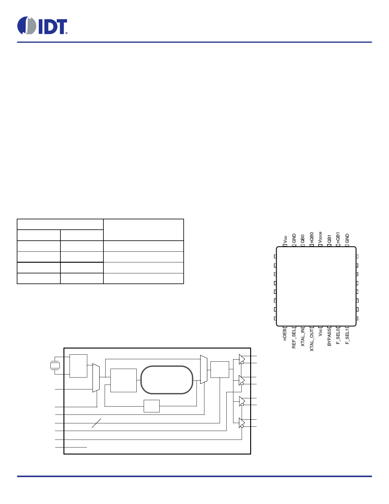
Pin Assignment
32 31 30 29 28 27 26 25
VDD 1
24 IREF
nc 2
VDDA 3
nc 4
841N254B
32-lead VFQFN
K Package
23 GND
22 nQA0
21 QA0
GND 5 5mm x 5mm x 0.925mm 20 VDDOA
package body
REF_CLK 6
Top View
19 nQA1
nOEA 7
18 QA1
VDD 8
17 GND
9 10 11 12 13 14 15 16
XTAL_IN
XTAL_OUT
REF_CLK
REF_SEL
BYPASS
F_SEL[0:1]
nOEA
nOEB
IREF
OSC 0
Pulldown
Pulldown
Pulldown
Pulldown
Pulldown
Pulldown
1
2
PFD
&
LPF
FemtoClock® NG
VCO
625MHz
1
÷N
0
÷25
QA0
nQA0
QA1
nQA1
QB0
nQB0
QB1
nQB1
LVDS
LVDS
HCSL
HCSL
©2016 Integrated Device Technology, Inc..
1
Revision B, May 23, 2016
1 page 
841N254B Datasheet
Table 4C. LVDS 3.3V DC Characteristics, VDD = VDDOA = 3.3V ± 5% or 2.5V ± 5%, TA = -40°C to 85°C
Symbol Parameter
Test Conditions
Minimum
Typical
Maximum
VOD
VOD
VOS
VOS
Differential Output Voltage
VOD Magnitude Change
Offset Voltage
VOS Magnitude Change
200 550
50
1.1 1.3
50
Units
mV
mV
V
mV
Table 5. Crystal Characteristics
Parameter
Mode of Oscillation
Frequency
Equivalent Series Resistance (ESR)
Shunt Capacitance
Test Conditions
Minimum
Typical
Fundamental
25
Maximum
80
7
Units
MHz
pF
©2016 Integrated Device Technology, Inc.
5
Revision B, May 23, 2016
5 Page 
Parameter Measurement Information, continued
nQA[0:1]
20%
QA[0:1]
80%
tR
HCSL Differential Measurement Points for Rise/Fall Time LVDS Rise/Fall Time
841N254B Datasheet
80%
tF
VOD
20%
Single-ended Measurement Points for Delta Cross Point
Single-ended Measurement Points for Absolute Cross
Point/Swing
Offset Voltage Setup
©2016 Integrated Device Technology, Inc.
Differential Output Voltage Setup
11 Revision B, May 23, 2016
11 Page | ||
| Páginas | Total 24 Páginas | |
| PDF Descargar | [ Datasheet 841N254B.PDF ] | |
Hoja de datos destacado
| Número de pieza | Descripción | Fabricantes |
| 841N254B | NG Crystal-to-LVDS/ HCSL Clock Synthesizer | IDT |
| Número de pieza | Descripción | Fabricantes |
| SLA6805M | High Voltage 3 phase Motor Driver IC. |
Sanken |
| SDC1742 | 12- and 14-Bit Hybrid Synchro / Resolver-to-Digital Converters. |
Analog Devices |
|
DataSheet.es es una pagina web que funciona como un repositorio de manuales o hoja de datos de muchos de los productos más populares, |
| DataSheet.es | 2020 | Privacy Policy | Contacto | Buscar |