|
|
|
PDF MAX14821 Data sheet ( Hoja de datos )
| Número de pieza | MAX14821 | |
| Descripción | IO-Link Device Transceiver | |
| Fabricantes | Maxim Integrated | |
| Logotipo | ||
Hay una vista previa y un enlace de descarga de MAX14821 (archivo pdf) en la parte inferior de esta página. Total 30 Páginas | ||
|
No Preview Available !
MAX14821
IO-Link Device Transceiver
General Description
The MAX14821 transceiver is suitable for IO-Link®
devices and 24V binary sensors/actuators. All specified
IO-Link data rates are supported. In IO-Link applications,
the transceiver acts as the physical layer interface to
a microcontroller running the data-link layer protocol.
Additional 24V digital inputs and outputs are provided.
Two internal linear regulators generate common sensor
and actuator power requirements: 5V and 3.3V.
On-board C/Q and DO drivers are independently configurable
for push-pull, high-side (PNP), or low-side (NPN) operation.
The device detects the IO-Link C/Q wake-up condition
and generates a wake-up signal on the active-low WU
output. The C/Q and DI inputs have selectable current
loads for use in actuators.
An SPI™ interface allows configuration and monitoring
of the device. Extensive alarm conditions are detected
and communicated through the IRQ output and the SPI
interface. The device features reverse-polarity, short-circuit,
and thermal protection. All power lines are monitored for
undervoltage conditions.
The C/Q and DO drivers are specified for sourcing/sinking
up to 100mA.
The device is available in a 2.5mm x 2.5mm, 25-pin wafer-
level package (WLP) and a 4mm x 4mm, 24-pin TQFN
package. Both are specified over the extended -40NC to
+85NC temperature range.
Benefits and Features
●● Standards Compliance Ensures Future-Proof Solutions
• IO-Link Versions 1.0 and 1.1.2
• IEC IEC61131.9 SDCI
●● High Configurability and Integration Reduces SKUs
• Push-Pull, PNP, or NPN Driver Configuration
• Supports COM1, COM2, and COM3 Data Rates
• SPI Interface for Control and Monitoring
• 2.5V to 5V Logic Interface Levels
• Auxiliary 24V, 100mA Digital Output (DO)
• Auxiliary 24V Digital Input (DI)
• 100mA Specified C/Q output Drive
• Integrated 5V and 3.3V Regulators
●● Integrated Protection Enables Robust Solutions
• Extensive Fault-Monitoring and Reporting
• Reverse-Polarity and Short-Circuit Protection on
All 24V Outputs/Inputs
• Reverse-Polarity Protected 24V Supply Output
-40°C to +105°C Operating Temperature Range
●● Small Package Supports Sensor Miniaturization
• 2.5mm x 2.5mm WLP and 4mm x 4mm TQFN
Package
Applications
IO-Link Sensors Industrial Sensors and Actuators
IO-Link Actuators
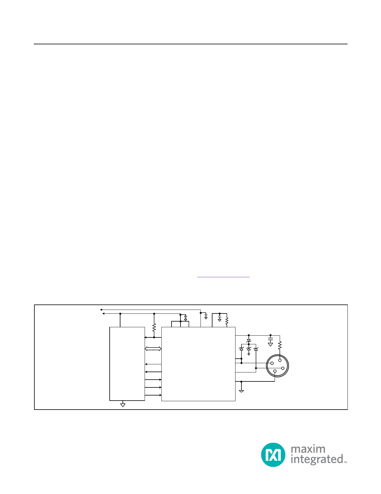
Typical Operating Circuit
Ordering Information appears at end of data sheet.
5V
3.3V
10kΩ
VCC
GPIO2
SPI
MICROCONTROLLER
IRQ
RX
TX
RTS
GND
GPIO1
0.1µF
0.1µF
1µF
10Ω
VL TXQ LDO33 V5 LDOIN
UV
VP
VCC
WU
RX
TXC
TXEN
LO
MAX14821
DO
DI
C/Q
GND
1µF
0.8Ω
L+
1
2
4
3
L-
IO-Link is a registered trademark of Profibus User Organization (PNO).
SPI is a trademark of Motorola, Inc.
19-5916; Rev 6; 12/15
1 page 
MAX14821
IO-Link Device Transceiver
DC Electrical Characteristics (continued)
(VCC = 18V to 36V, VL = 2.3V to 5.5V, VGND = 0V; all logic inputs at VL or GND; TA = -40NC to +85NC, unless otherwise noted. Typical
values are at VCC = 24V, VL = 3.3V, and TA = +25NC, unless otherwise noted.) (Note 2)
PARAMETER
SYMBOL
CONDITIONS
DO Weak Pulldown Current
IPDDO
DO driver disabled, VCC = 36V,
VDO = (VCC - 1V)
DI Weak Pulldown Current
IPDDI
DI load disabled, VCC = 36V,
VDI = (VCC - 1V)
C/Q Input Capacitance
CC/Q
C/Q driver disabled
DO Input Capacitance
CDO
DO driver disabled
DI Input Capacitance
CDI
C/Q, DI CURRENT SINK
C/Q Load Current
ILLM_C/Q
C/Q load enabled
(C/QLoad = 1)
0V P VC/Q P 5V
5V P VC/Q
DI Load Current
ILLM_DI
DI load enabled
(DiLoad = 1)
0V P VDI P 5V
9V P VDI
LOGIC INPUTS (TXC, TXQ, TXEN, LO, CS, SDI, SCLK)
Logic-Input Voltage Low
VIL
Logic -Input Voltage High
VIH
Logic-Input Leakage Current
ILEAK
Logic-Input Capacitance
CIN
LOGIC OUTPUTS (RX, WU, LI, UV, SDO, IRQ)
Logic-Output Voltage Low
VOL
Logic input = GND or VL
IOUT = -5mA
MIN
40
50
0
5
0
6
0.3 x
VL
-1
TYP
40
40
20
6.6
7.5
5
MAX
120
UNITS
FA
300 FA
pF
pF
pF
9
9
mA
9
mA
9
0.7 x
VL
+1
0.4
V
V
FA
pF
V
Logic-Output Voltage High
VOHRX,
VOHWU, VOHLI,
VOHSDO,
VOHIRQ,
IOUT = 5mA (Note 3)
VL -
0.6
V
SDO Leakage Current
THERMAL SHUTDOWN
Thermal-Warning Threshold
Thermal-Warning Threshold
Hysteresis
Thermal-Shutdown Threshold
Thermal-Shutdown Hysteresis
ILK_SDO
SDO disabled, SDO = GND or VL
Die temperature rising, OTemp bit is set
Die temperature falling, OTemp bit is
cleared
Die temperature rising
-1 +1
+115
20
+150
20
FA
NC
NC
NC
NC
www.maximintegrated.com
Maxim Integrated │ 5
5 Page 
MAX14821
IO-Link Device Transceiver
Typical Operating Characteristics
(VCC = 24V, LDOIN = VP, VL = LDO33, C/Q and DO in push-pull configuration, TA = +25NC, unless otherwise noted.)
C/Q DRIVER OUTPUT HIGH
vs. LOAD CURRENT
7
6
5
4
3 TA = +85°C
2 TA = -40°C TA = +25°C
1
0
0 25 50 75 100 125
LOAD CURRENT (mA)
DO DRIVER OUTPUT HIGH
vs. LOAD CURRENT
7
6
5
4
3
2
TA = -40°C TA = +25°C
TA = +85°C
1
0
0 25 50 75 100 125
LOAD CURRENT (mA)
C/Q DRIVER PROPAGATION DELAY
vs. TEMPERATURE (HiSlew = 0)
1.30
1.28
1.26
1.24
1.22
1.20
1.18
1.16
1.14
1.12 TXEN = VL
TXC = TXQ
1.10
-45 -30 -15 0 15 30 45 60 75 90
TEMPERATURE (°C)
C/Q DRIVER OUTPUT LOW
vs. SINK CURRENT
7
6
5
4
TA = +85°C
3 TA = +25°C
2 TA = -40°C
1
0
0 25 50 75 100 125 150 175
SINK CURRENT (mA)
DO DRIVER OUTPUT LOW
vs. SINK CURRENT
7
6
5
4 TA = +85°C
3 TA = +25°C
TA = -40°C
2
1
0
0 25 50 75 100 125 150 175
SINK CURRENT (mA)
C/Q DRIVER PROPAGATION DELAY
vs. TEMPERATURE (HiSlew = 1)
0.46
0.45
0.44
0.43
0.42
0.41
0.40
0.39 TXEN = VL
TXC = TXQ
0.38
-45 -30 -15 0 15 30 45 60 75 90
TEMPERATURE (°C)
www.maximintegrated.com
Maxim Integrated │ 11
11 Page | ||
| Páginas | Total 30 Páginas | |
| PDF Descargar | [ Datasheet MAX14821.PDF ] | |
Hoja de datos destacado
| Número de pieza | Descripción | Fabricantes |
| MAX1482 | Slew-Rate-Limited RS-485 Transceivers | Maxim Integrated |
| MAX14820 | IO-Link Device Transceiver | Maxim Integrated |
| MAX14821 | IO-Link Device Transceiver | Maxim Integrated |
| MAX14824 | IO-Link Master Transceiver | Maxim Integrated |
| Número de pieza | Descripción | Fabricantes |
| SLA6805M | High Voltage 3 phase Motor Driver IC. |
Sanken |
| SDC1742 | 12- and 14-Bit Hybrid Synchro / Resolver-to-Digital Converters. |
Analog Devices |
|
DataSheet.es es una pagina web que funciona como un repositorio de manuales o hoja de datos de muchos de los productos más populares, |
| DataSheet.es | 2020 | Privacy Policy | Contacto | Buscar |