|
|
|
PDF HMC394LP4E Data sheet ( Hoja de datos )
| Número de pieza | HMC394LP4E | |
| Descripción | GaAs HBT PROGRAMMABLE 5-BIT COUNTER | |
| Fabricantes | Analog Devices | |
| Logotipo | ||
Hay una vista previa y un enlace de descarga de HMC394LP4E (archivo pdf) en la parte inferior de esta página. Total 11 Páginas | ||
|
No Preview Available !
v09.0114
Typical Applications
4 Programmable divider for offset synthesizer
and variable divide by N applications:
• Satellite Communication Systems
• Point-to-Point and Point-to-Multi-Point Radios
• LMDS
• SONET
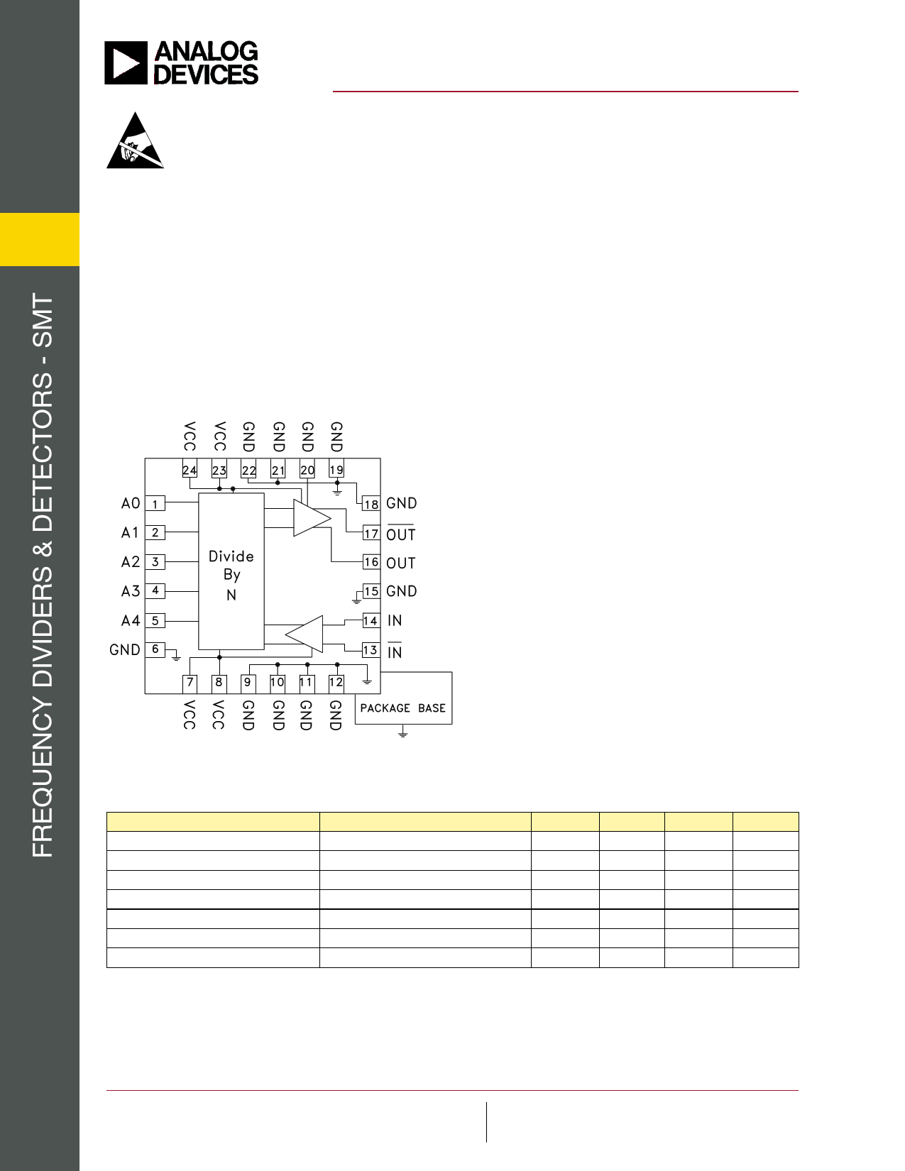
Functional Diagram
HMC394LP4 / 394LP4E
GaAs HBT PROGRAMMABLE
5-BIT COUNTER, DC - 2.2 GHz
Features
SSB Phase Noise: -153 dBc/Hz @ 100 kHz
Selectable Division from 2 to 32
Parallel 5-Bit Control
Wide Input Power Range: -20 to +10 dBm
24 Lead 4x4mm QFN Package: 9 mm²
General Description
The HMC394LP4 & HMC394LP4E are low noise
GaAs HBT programmable 5-bit counters in 4 x
4mm leadless surface mount packages. This device
allows continuous division from N= 2 to 32 at input
frequencies up to 2.2 GHz. The output voltage swing is
800 mV with a duty cycle inversely proportional to N.
The low additive SSB phase noise of -153 dBc/Hz at
100 KHz offset makes this counter an excellent choice
for low noise synthesizer applications.
Electrical Specifications, TA = +25° C, 50 Ohm System, Vcc= 5V
Parameter
Conditions
Maximum Input Frequency
Minimum Input Frequency
Sine Wave Input [1]
Input Power Range
Fin = 0.1 to 2.2 GHz
Output Power
Divide-by-2
SSB Phase Noise
Fin = 1 GHz, N = 4
Output Transition Time
Supply Current (Icc)
1. Divider will operate down to DC for square-wave input signal.
Min.
2.2
-15
Typ.
>-20
4
-153
100
194
Max.
0.1
+10
Units
GHz
GHz
dBm
dBm
dBc/Hz
ps
mA
4-1
IrrlTiniecgrfaseohpdntrsFeomsemnoaosfatiisirbtrohkingislprirtdayafrunnpiirsdtcnaeairdrsetesihegsb,esuiysdmdttheimebaeredtypldmlbiiAcvtyaranPayeAtadiorlhnroeenaymgsoluooanlDargtrkeofenDrsvtoh:eidamcevr9eAreicwistt7etsopihssie8usepfspop-beulrr2.nelioiacdtSlp5iseepecavu0rreetsetcya-deiinofo3,iyocftnno3atoprhtrida4eboSftienoere3srnuraertaspscsnoupcyrb:peujipcernHFoaatcfirtvttareieientttnoxgt:aoteicnw:rtPmhdiegn9aeehhnrn7rteMgssotls.8eiaonoibwf-cfel2Aieptrh:n.5aooatH9ue0lwoton7g-wntas38oDeotvvi3e-creev2eo7ri,.ct5h3eNCnes0oor.o- r3pFOPA3Ooohpn4rrorpe3danlpiTeectreii:aorocc7treihnO8o,n,1nnaod-2S3lp-eo02lulgpii9vnpyAse-pe4rW@oly7par,a0hthy:ta0i,Pantw•PtdhiR.wOtoOetnoor.w.decBa:ep.odo1hrlax-mo,i8ctn9Cet0l1ii0tn0hoe-e6rAe.d,caNleNmtoArwosmsL:rwOwfAowGonro.d-aadDln,o,agMMloADgAe.0cv02oic01me68s22,-49In10c.6,
1 page 
v09.0114
Absolute Maximum Ratings
RF Input (Vcc = +5V)
Vcc
VLogic
Maximum Channel Temperature
Continuous Pdiss (T = 85 °C)
(derate 55 mW/°C above 85 °C)
Thermal Resistance (u j-c ) Junction to
Case (Ground Paddle)
Storage Temperature
+13 dBm
+5.5V
-1.6 to -1.2 Vcc
135 °C
1.155 W
21.5 °C/W
-65 to +150°C
Operating Temperature
+55 to +85°C
Outline Drawing
HMC394LP4 / 394LP4E
GaAs HBT PROGRAMMABLE
5-BIT COUNTER, DC - 2.2 GHz
ELECTROSTATIC SENSITIVE DEVICE
OBSERVE HANDLING PRECAUTIONS
4
NOTES:
1. LEADFRAME MATERIAL: COPPER ALLOY
2. DIMENSIONS ARE IN INCHES [MILLIMETERS]
3. LEAD SPACING TOLERANCE IS NON-CUMULATIVE.
4. PAD BURR LENGTH SHALL BE 0.15mm MAXIMUM.
PAD BURR HEIGHT SHALL BE 0.05mm MAXIMUM.
5. PACKAGE WARP SHALL NOT EXCEED 0.05mm.
6. ALL GROUND LEADS AND GROUND PADDLE MUST BE
SOLDERED TO PCB RF GROUND.
7. REFER TO HITTITE APPLICATION NOTE FOR SUGGESTED
LAND PATTERN.
Package Information
Part Number
Package Body Material
HMC394LP4
Low Stress Injection Molded Plastic
Lead Finish
Sn/Pb Solder
HMC394LP4E RoHS-compliant Low Stress Injection Molded Plastic
[1] Max peak reflow temperature of 235 °C
[2] Max peak reflow temperature of 260 °C
[3] 4-Digit lot number XXXX
100% matte Sn
MSL Rating
MSL1 [1]
MSL1 [2]
Package Marking [3]
H394
XXXX
H394
XXXX
IrrlTiniecgrfaseohpdntrsFeomsemnoaosfatiisirbtrohkingislprirtdayafrunnpiirsdtcnaeairdrsetesihegsb,esuiysdmdttheimebaeredtypldmlbiiAcvtyaranPayeAtadiorlhnroeenaymgsoluooanlDargtrkeofenDrsvtoh:eidamcevr9eAreicwistt7etsopihssie8usepfspop-beulrr2.nelioiacdtSlp5iseepecavu0rreetsetcya-deiinofo3,iyocftnno3atoprhtrida4eboSftienoere3srnuraertaspscsnoupcyrb:peujipcernHFoaatcfirtvttareieientttnoxgt:aoteicnw:rtPmhdiegn9aeehhnrn7rteMgssotls.8eiaonoibwf-cfel2Aieptrh:n.5aooatH9ue0lwoton7g-wntas38oDeotvvi3e-creev2eo7ri,.ct5h3eNCnes0oor.o- r3pFOPA3Ooohpn4rrorpe3danlpiTeectreii:aorocc7treihnO8o,n,1nnaod-2S3lp-eo02lulgpii9vnpyAse-pe4rW@oly7par,a0hthy:ta0i,Pantw•PtdhiR.wOtoOetnoor.w.decBa:ep.odo1hrlax-mo,i8ctn9Cet0l1ii0tn0hoe-e6rAe.d,caNleNmtoArwosmsL:rwOwfAowGonro.d-aadDln,o,agMMloADgAe.0cv02oic01me68s22,-49In10c.6,
4-4
5 Page 
v09.0114
HMC394LP4 / 394LP4E
GaAs HBT PROGRAMMABLE
5-BIT COUNTER, DC - 2.2 GHz
CMOS/TTL Input Characteristics
Maximum Input Logic “0” Voltage (VIL MAXIMUM) = 1.1V @ 10 uA.
Minimum Input Logic “1” Voltage (VIH MINIMUM) = 1.8V @ 500 uA.
Input IV characteristics for the logic inputs (A0-A4) are shown below:
0.4
V
0.2 IL MAX
V
IH MIN
0
-0.2
-0.4
-0.6
-0.8
0
1234
Input Voltage (V)
5
4
IrrlTiniecgrfaseohpdntrsFeomsemnoaosfatiisirbtrohkingislprirtdayafrunnpiirsdtcnaeairdrsetesihegsb,esuiysdmdttheimebaeredtypldmlbiiAcvtyaranPayeAtadiorlhnroeenaymgsoluooanlDargtrkeofenDrsvtoh:eidamcevr9eAreicwistt7etsopihssie8usepfspop-beulrr2.nelioiacdtSlp5iseepecavu0rreetsetcya-deiinofo3,iyocftnno3atoprhtrida4eboSftienoere3srnuraertaspscsnoupcyrb:peujipcernHFoaatcfirtvttareieientttnoxgt:aoteicnw:rtPmhdiegn9aeehhnrn7rteMgssotls.8eiaonoibwf-cfel2Aieptrh:n.5aooatH9ue0lwoton7g-wntas38oDeotvvi3e-creev2eo7ri,.ct5h3eNCnes0oor.o- r3pFOPA3Ooohpn4rrorpe3danlpiTeectreii:aorocc7treihnO8o,n,1nnaod-2S3lp-eo02lulgpii9vnpyAse-pe4rW@oly7par,a0hthy:ta0i,Pantw•PtdhiR.wOtoOetnoor.w.decBa:ep.odo1hrlax-mo,i8ctn9Cet0l1ii0tn0hoe-e6rAe.d,caNleNmtoArwosmsL:rwOwfAowGonro.d-aadDln,o,agMMloADgAe.0cv02oic01me68s22,-49In10c.6,
4 - 10
11 Page | ||
| Páginas | Total 11 Páginas | |
| PDF Descargar | [ Datasheet HMC394LP4E.PDF ] | |
Hoja de datos destacado
| Número de pieza | Descripción | Fabricantes |
| HMC394LP4 | GaAs HBT PROGRAMMABLE 5-BIT COUNTER | Hittite Microwave Corporation |
| HMC394LP4E | GaAs HBT PROGRAMMABLE 5-BIT COUNTER | Analog Devices |
| Número de pieza | Descripción | Fabricantes |
| SLA6805M | High Voltage 3 phase Motor Driver IC. |
Sanken |
| SDC1742 | 12- and 14-Bit Hybrid Synchro / Resolver-to-Digital Converters. |
Analog Devices |
|
DataSheet.es es una pagina web que funciona como un repositorio de manuales o hoja de datos de muchos de los productos más populares, |
| DataSheet.es | 2020 | Privacy Policy | Contacto | Buscar |