|
|
|
PDF HPLR3103 Data sheet ( Hoja de datos )
| Número de pieza | HPLR3103 | |
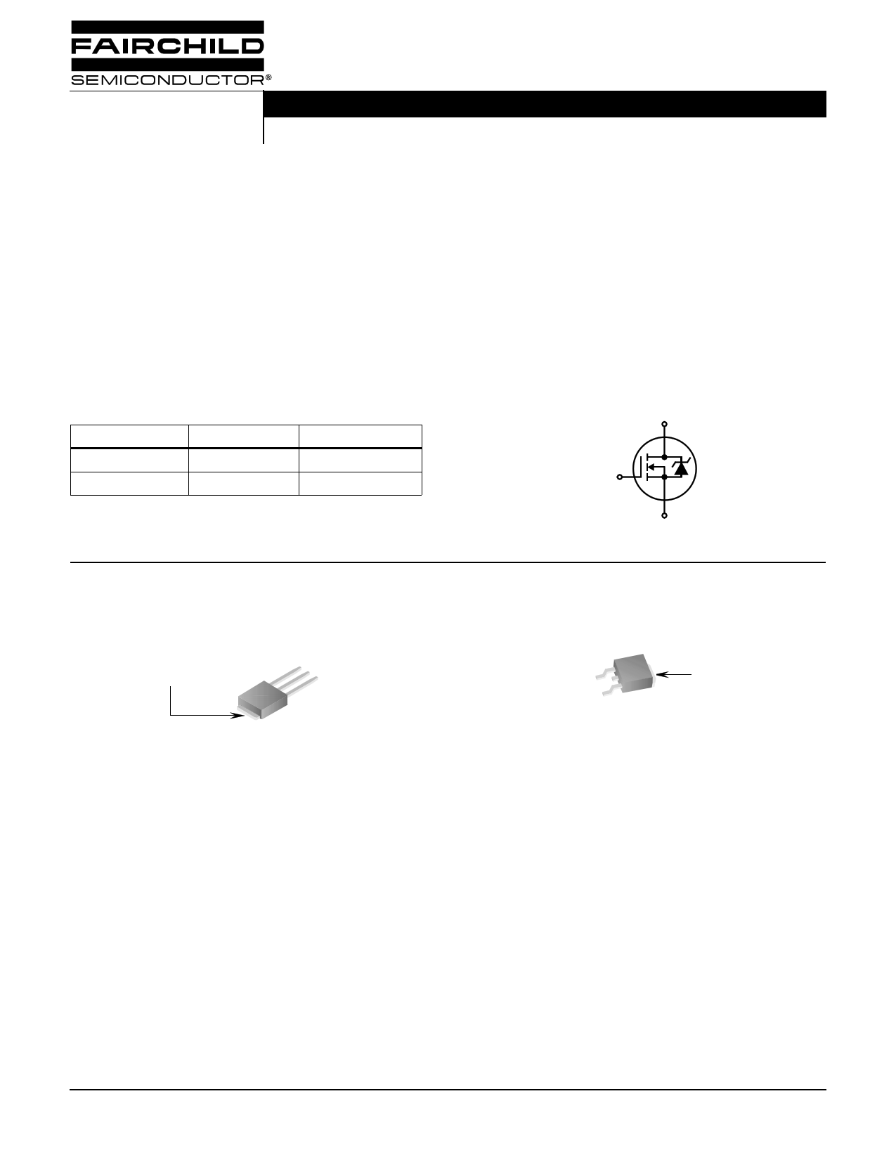
| Descripción | 52A/ 30V/ 0.019 Ohm/ N-Channel Logic Level/ Power MOSFETs | |
| Fabricantes | Fairchild Semiconductor | |
| Logotipo | ||
Hay una vista previa y un enlace de descarga de HPLR3103 (archivo pdf) en la parte inferior de esta página. Total 7 Páginas | ||
|
No Preview Available !
Data Sheet
HPLR3103, HPLU3103
December 2001
52A, 30V, 0.019 Ohm, N-Channel Logic
Level, Power MOSFETs
These are N-Channel enhancement mode silicon gate
power field effect transistors. They are advanced power
MOSFETs designed, tested, and guaranteed to withstand a
specified level of energy in the breakdown avalanche mode
of operation. All of these power MOSFETs are designed for
applications such as switching regulators, switching
converters, motor drivers, relay drivers, and drivers for high
power bipolar switching transistors requiring high speed and
low gate drive power. These types can be operated directly
from integrated circuits.
Ordering Information
PART NUMBER
PACKAGE
BRAND
HPLU3103
TO-251AA
HP3103
HPLR3103
TO-252AA
HP3103
NOTE: When ordering, use the entire part number. Add the suffix T
to obtain the TO-252AA variant in tape and reel, e.g., HPLR3103T.
Packaging
JEDEC TO-251AA
DRAIN
(FLANGE)
SOURCE
DRAIN
GATE
Features
• Logic Level Gate Drive
• 52A†, 30V
• Low On-Resistance, rDS(ON) = 0.019Ω
• UIS Rating Curve
• Related Literature
- TB334, “Guidelines for Soldering Surface Mount
Components to PC Boards”
† Calculated continuous current based on maximum allowable junction
temperature. Package limited to 20A continuous, see Figure 9.
Symbol
D
G
S
JEDEC TO-252AA
GATE
SOURCE
DRAIN
(FLANGE)
©2001 Fairchild Semiconductor Corporation
HPLR3103, HPLU3103 Rev. B
1 page 
HPLR3103, HPLU3103
Typical Performance Curves (Continued)
60 1000
If R = 0
tAV = (L)(IAS)/(1.3*RATED IASVDSS - VDD)
If R ≠ 0
45 tAV = (L/R)ln[(IAS*R)/(1.3*RATED BVDSS - VDD) +1]
100 EAS POINT
30 STARTING TJ = 25oC
10
15 STARTING TJ = 150oC
0
25 50 75 100 125 150
TC, CASE TEMPERATURE (oC)
FIGURE 9. MAXIMUM CONTINUOUS DRAIN CURRENT vs
CASE TEMPERATURE
1
0.001
0.01
0.1
1
10
tAV, TIME IN AVALANCHE (ms)
FIGURE 10. UNCLAMPED INDUCTIVE SWITCHING
CAPABILITY
100
2
DUTY CYCLE - DESCENDING ORDER
1 0.5
0.2
0.1
0.05
0.02
0.01
0.1
PDM
0.01
10-5
SINGLE PULSE
10-4
t1
NOTES:
t2
DUTY FACTOR: D = t1/t2
PEAK TJ = PDM x ZθJC x RθJC + TC
10-3
10-2
10-1
t, RECTANGULAR PULSE DURATION (s)
100
101
FIGURE 11. NORMALIZED MAXIMUM TRANSIENT THERMAL IMPEDANCE
Test Circuits and Waveforms
VDS
VARY tP TO OBTAIN
REQUIRED PEAK IAS
VGS
tP
0V
RG
L
DUT
+
VDD
-
IAS
0.01Ω
0
tP
IAS
BVDSS
VDS
VDD
tAV
FIGURE 12. UNCLAMPED ENERGY TEST CIRCUIT
FIGURE 13. UNCLAMPED ENERGY WAVEFORMS
©2001 Fairchild Semiconductor Corporation
HPLR3103, HPLU3103 Rev. B
5 Page | ||
| Páginas | Total 7 Páginas | |
| PDF Descargar | [ Datasheet HPLR3103.PDF ] | |
Hoja de datos destacado
| Número de pieza | Descripción | Fabricantes |
| HPLR3103 | 52A/ 30V/ 0.019 Ohm/ N-Channel Logic Level/ Power MOSFETs | Fairchild Semiconductor |
| HPLR3103 | 52A/ 30V/ 0.019 Ohm/ N-Channel Logic Level/ Power MOSFETs | Intersil Corporation |
| Número de pieza | Descripción | Fabricantes |
| SLA6805M | High Voltage 3 phase Motor Driver IC. |
Sanken |
| SDC1742 | 12- and 14-Bit Hybrid Synchro / Resolver-to-Digital Converters. |
Analog Devices |
|
DataSheet.es es una pagina web que funciona como un repositorio de manuales o hoja de datos de muchos de los productos más populares, |
| DataSheet.es | 2020 | Privacy Policy | Contacto | Buscar |