|
|
|
PDF HMC294 Data sheet ( Hoja de datos )
| Número de pieza | HMC294 | |
| Descripción | GaAs MMIC DOUBLE-BALANCED MIXER/ 25 - 40 GHz | |
| Fabricantes | Hittite Microwave Corporation | |
| Logotipo | ||
Hay una vista previa y un enlace de descarga de HMC294 (archivo pdf) en la parte inferior de esta página. Total 6 Páginas | ||
|
No Preview Available !
v01.0300
MICROWAVE CORPORATION
HMC294
GaAs MMIC DOUBLE-BALANCED
MIXER, 25 - 40 GHz
Typical Applications
The HMC294 is ideal for:
• Microwave Pt to Pt Radios
• LMDS
• SATCOM
Features
Input IP3: +20 dBm
LO / RF Isolation: 27 dB
Passive: No DC Bias Required
Small Size: 0.88 mm x 1.93 mm
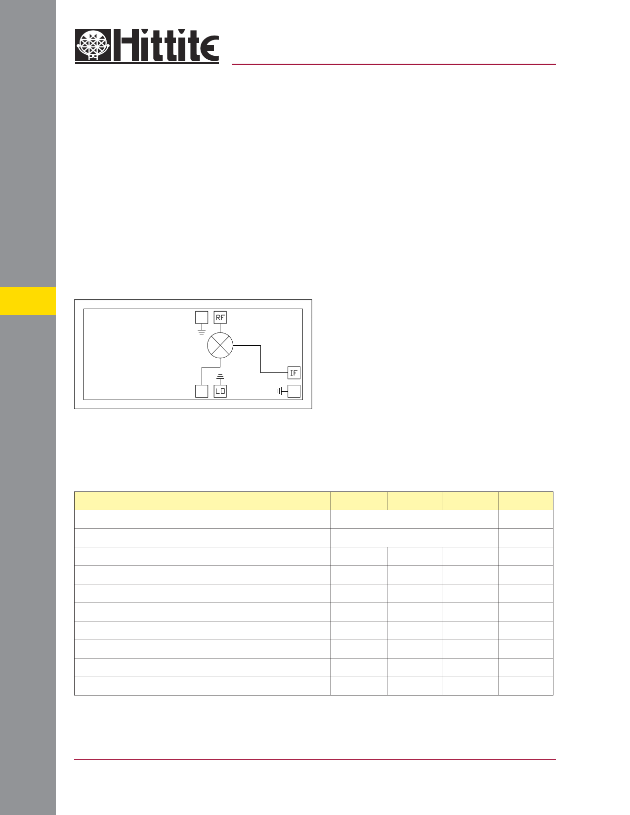
Functional Diagram
5
General Description
The HMC294 chip is a miniature passive GaAs
MMIC double-balanced mixer which can be used
as an upconverter or downconverter from 25 - 40
GHz in a small chip area of 1.70 mm2. Excellent
isolations are provided by on-chip baluns, which
require no external components and no DC bias.
All data is measured with the chip in a 50 ohm
test fixture connected via 0.076 mm (3 mil) gold
ribbon of minimal length <0.31 mm (<12 mils).
Electrical Specifications, TA = +25° C, LO Drive = +14 dBm
Parameter
Frequency Range, RF & LO
Frequency Range, IF
Conversion Loss
Noise Figure (SSB)
LO to RF Isolation
LO to IF Isolation
RF to IF Isolation
IP3 (Input)
IP2 (Input)
1 dB Gain Compression (Input)
Min. Typ.
25 - 40
DC - 2
10
10
22 27
31 38
27 33
15 20
24 35
9 12
Max.
13
13
Units
GHz
GHz
dB
dB
dB
dB
dB
dBm
dBm
dBm
5 - 76
For price, delivery, and to place orders, please contact Hittite Microwave Corporation:
12 Elizabeth Drive, Chelmsford, MA 01824 Phone: 978-250-3343 Fax: 978-250-3373
Order Online at www.hittite.com
1 page 
v01.0300
MICROWAVE CORPORATION
HMC294
GaAs MMIC DOUBLE-BALANCED
MIXER, 25 - 40 GHz
MIC Assembly Techniques
Ribbon Bond
Ribbon Bond
5
Mounting & Bonding Techniques for Millimeterwave GaAs MMICs
The die should be attached directly to the ground plane eutectically or with conductive epoxy (see HMC general Handling, Mounting,
Bonding Note).
50 Ohm Microstrip transmission lines on 0.127mm (5 mil) thick alumina thin film substrates are recommended for bringing RF to and
from the chip (Figure 1). If 0.254mm (10 mil) thick alumina thin film substrates must be used, the die should be raised 0.150mm (6
mils) so that the surface of the die is coplanar with the surface of the substrate. One way to accomplish this is to attach the 0.102mm (4
mil) thick die to a 0.150mm (6 mil) thick molybdenum heat spreader (moly-tab) which is then attached to the ground plane (Figure 2).
Microstrip substrates should be brought as close to the die as possible in order to minimize bond wire length. Typical die-to-substrate
spacing is 0.076mm (3 mils). Gold ribbon of 0.076 mm x 0.013 mm (3 mil x 0.5 mil) and minimal length <0.31 mm (<12 mils) is recom-
mended to minimize inductance on the RF ports.
5 - 80
For price, delivery, and to place orders, please contact Hittite Microwave Corporation:
12 Elizabeth Drive, Chelmsford, MA 01824 Phone: 978-250-3343 Fax: 978-250-3373
Order Online at www.hittite.com
5 Page | ||
| Páginas | Total 6 Páginas | |
| PDF Descargar | [ Datasheet HMC294.PDF ] | |
Hoja de datos destacado
| Número de pieza | Descripción | Fabricantes |
| HMC290 | 2 dB LSB GaAs MMIC 2-BIT DIGITAL ATTENUATOR/ 0.7 - 4.0 GHz | Hittite Microwave Corporation |
| HMC291 | 4 dB LSB GaAs MMIC 2-BIT DIGITAL ATTENUATOR/ 0.7 - 4.0 GHz | Hittite Microwave Corporation |
| HMC291SE | 4 dB LSB SILICON 2-BIT POSITIVE CONTROL DIGITAL ATTENUATOR | Analog Devices |
| HMC292 | GaAs MMIC DOUBLE-BALANCED MIXER/ 18 - 32 GHz | Hittite Microwave Corporation |
| Número de pieza | Descripción | Fabricantes |
| SLA6805M | High Voltage 3 phase Motor Driver IC. |
Sanken |
| SDC1742 | 12- and 14-Bit Hybrid Synchro / Resolver-to-Digital Converters. |
Analog Devices |
|
DataSheet.es es una pagina web que funciona como un repositorio de manuales o hoja de datos de muchos de los productos más populares, |
| DataSheet.es | 2020 | Privacy Policy | Contacto | Buscar |