|
|
|
PDF ZL50235GDC Data sheet ( Hoja de datos )
| Número de pieza | ZL50235GDC | |
| Descripción | 16 Channel Voice Echo Canceller | |
| Fabricantes | ETC | |
| Logotipo | ||
Hay una vista previa y un enlace de descarga de ZL50235GDC (archivo pdf) en la parte inferior de esta página. Total 43 Páginas | ||
|
No Preview Available !
ZL50235
16 Channel Voice Echo Canceller
Data Sheet
Features
• Independent multiple channels of echo
cancellation; from 16 channels of 64 ms to 8
channels of 128 ms with the ability to mix
channels at 128 ms or 64 ms in any combination
• Independent Power Down mode for each group of
2 channels for power management
• Fully compliant to ITU-T G.165, G.168 (2000) and
(2002) specifications
• Passed AT&T voice quality testing for carrier
grade echo cancellers
• Compatible to ST-BUS and GCI interfaces with
2 Mbps serial PCM data
• PCM coding, µ/A-Law ITU-T G.711 or sign
magnitude
• Per channel Fax/Modem G.164 2100 Hz or G.165
2100 Hz phase reversal Tone Disable
• Per channel echo canceller parameters control
• Transparent data transfer and mute
• Fast reconvergence on echo path changes
• Fully programmable convergence speeds
• Patented Advanced Non-Linear Processor with
high quality subjective performance
• Protection against narrow band signal divergence
and instability in high echo environments
VDD1 (3.3 V)
VSS
March 2006
Ordering Information
ZL50235/QCC
ZL50235/GDC
ZL50235QCG1
100 Pin LQFP Trays
208 Ball PBGA Trays
100 Pin LQFP* Trays, Bake & Drypack
*Pb Free Matte Tin
-40°C to +85°C
• +9 dB to -12 dB level adjusters (3 dB steps) at all
signal ports
• Offset nulling of all PCM channels
• 10 MHz or 20 MHz master clock operation
• 3.3 V IO pads and 1.8 V Logic core operation with
5 V tolerant inputs
• IEEE-1149.1 (JTAG) Test Access Port
• ZL50232, ZL50233, ZL50234 and ZL50235 have
same pinouts in both LQFP and LBGA packages
Applications
• Voice over IP network gateways
• Voice over ATM, Frame Relay
• T1/E1/J1 multichannel echo cancellation
• Wireless base stations
• Echo Canceller pools
• DCME, satellite and multiplexer system
VDD2 (1.8 V)
ODE
Rin
Sin
MCLK
Fsel
C4i
F0i
Serial
to
Parallel
PLL
Timing
Unit
Echo Canceller Pool
Group 0 Group 1 Group 2
ECA/ECB ECA/ECB ECA/ECB
Group 4 Group 5 Group 6
ECA/ECB ECA/ECB ECA/ECB
Group 3
ECA/ECB
Group 7
ECA/ECB
Parallel
to
Serial
Note:
Refer to Figure 4
for Echo Canceller
block diagram
Microprocessor Interface
Test Port
Rout
Sout
RESET
DS CS R/W A10-A0 DTA D7-D0 IRQ TMS TDI TDO TCK TRST
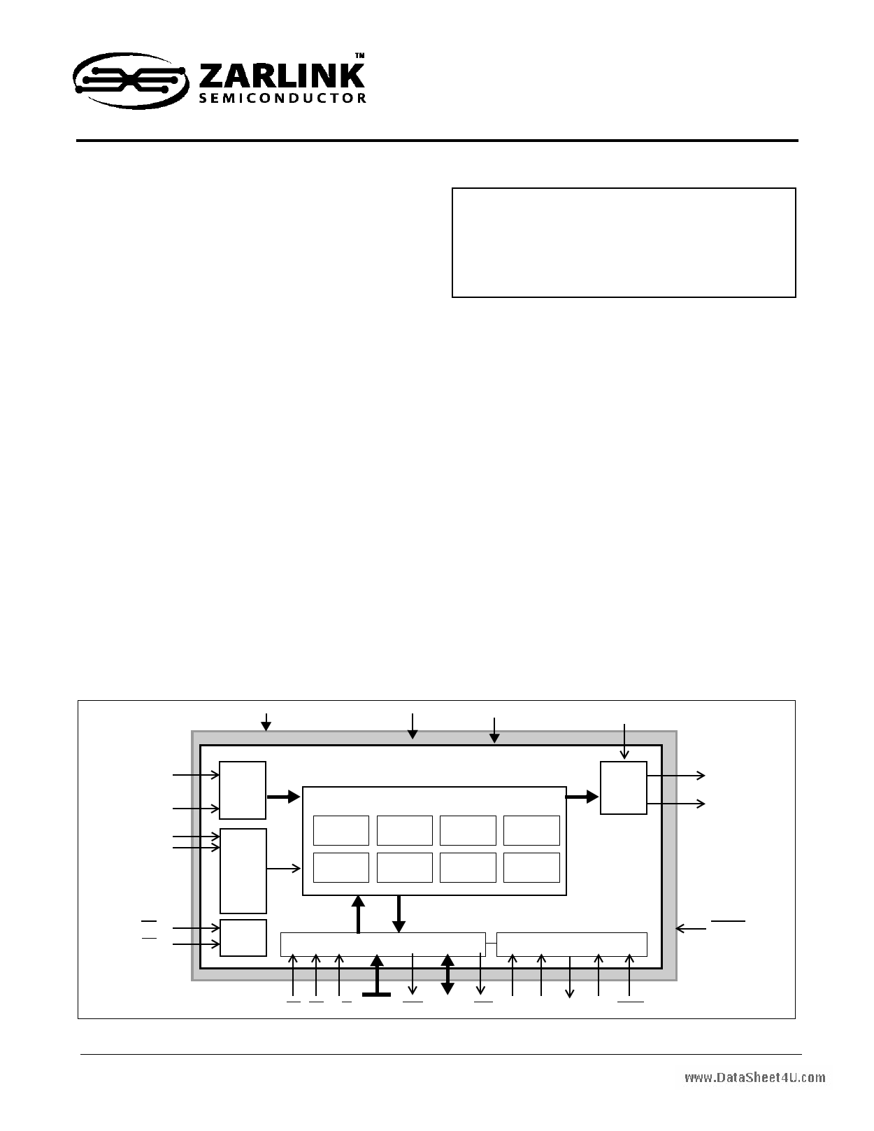
Figure 1 - ZL50235 Device Overview
1
Zarlink Semiconductor Inc.
Zarlink, ZL and the Zarlink Semiconductor logo are trademarks of Zarlink Semiconductor Inc.
Copyright 2003-2006, Zarlink Semiconductor Inc. All Rights Reserved.
1 page 
ZL50235
Data Sheet
List of Figures
Figure 1 - ZL50235 Device Overview . . . . . . . . . . . . . . . . . . . . . . . . . . . . . . . . . . . . . . . . . . . . . . . . . . . . . . . . . . . 1
Figure 2 - 100 Pin LQFP . . . . . . . . . . . . . . . . . . . . . . . . . . . . . . . . . . . . . . . . . . . . . . . . . . . . . . . . . . . . . . . . . . . . . 2
Figure 3 - 208 Ball LBGA . . . . . . . . . . . . . . . . . . . . . . . . . . . . . . . . . . . . . . . . . . . . . . . . . . . . . . . . . . . . . . . . . . . . . 3
Figure 4 - Functional Block Diagram . . . . . . . . . . . . . . . . . . . . . . . . . . . . . . . . . . . . . . . . . . . . . . . . . . . . . . . . . . . 10
Figure 5 - Disable Tone Detection . . . . . . . . . . . . . . . . . . . . . . . . . . . . . . . . . . . . . . . . . . . . . . . . . . . . . . . . . . . . . 13
Figure 6 - Normal Device Configuration (64 ms) . . . . . . . . . . . . . . . . . . . . . . . . . . . . . . . . . . . . . . . . . . . . . . . . . . 15
Figure 7 - Back-to-Back Device Configuration (64 ms) . . . . . . . . . . . . . . . . . . . . . . . . . . . . . . . . . . . . . . . . . . . . . 15
Figure 8 - Extended Delay Configuration (128 ms) . . . . . . . . . . . . . . . . . . . . . . . . . . . . . . . . . . . . . . . . . . . . . . . . 16
Figure 9 - ST-BUS and GCI Interface Channel Assignment for 2 Mbps Data Streams . . . . . . . . . . . . . . . . . . . . . 18
Figure 10 - Memory Mapping . . . . . . . . . . . . . . . . . . . . . . . . . . . . . . . . . . . . . . . . . . . . . . . . . . . . . . . . . . . . . . . . . 20
Figure 11 - Power Up Sequence Flow Diagram. . . . . . . . . . . . . . . . . . . . . . . . . . . . . . . . . . . . . . . . . . . . . . . . . . . 21
Figure 12 - The MU Profile. . . . . . . . . . . . . . . . . . . . . . . . . . . . . . . . . . . . . . . . . . . . . . . . . . . . . . . . . . . . . . . . . . . 27
Figure 13 - ST-BUS Timing at 2.048 Mbps . . . . . . . . . . . . . . . . . . . . . . . . . . . . . . . . . . . . . . . . . . . . . . . . . . . . . . 38
Figure 14 - GCI Interface Timing at 2.048 Mbps . . . . . . . . . . . . . . . . . . . . . . . . . . . . . . . . . . . . . . . . . . . . . . . . . . 39
Figure 15 - Output Driver Enable (ODE) . . . . . . . . . . . . . . . . . . . . . . . . . . . . . . . . . . . . . . . . . . . . . . . . . . . . . . . . 39
Figure 16 - Master Clock . . . . . . . . . . . . . . . . . . . . . . . . . . . . . . . . . . . . . . . . . . . . . . . . . . . . . . . . . . . . . . . . . . . . 39
Figure 17 - Motorola Non-Multiplexed Bus Timing. . . . . . . . . . . . . . . . . . . . . . . . . . . . . . . . . . . . . . . . . . . . . . . . . 40
5
Zarlink Semiconductor Inc.
5 Page 
ZL50235
Data Sheet
2.1 Adaptive Filter
The adaptive filter adapts to the echo path and generates an estimate of the echo signal. This echo estimate is then
subtracted from Sin. For each group of echo cancellers, the adaptive filter is a 1024 tap FIR adaptive filter which is
divided into two sections. Each section contains 512 taps providing 64 ms of echo estimation. In Normal
configuration, the first section is dedicated to channel A and the second section to channel B. In Extended Delay
configuration, both sections are cascaded to provide 128 ms of echo estimation in channel A. In Back-to Back
configuration, the first section is used in the receive direction and the second section is used in the transmit
direction for the same channel.
2.2 Double-Talk Detector
Double-Talk is defined as those periods of time when signal energy is present in both directions simultaneously.
When this happens, it is necessary to disable the filter adaptation to prevent divergence of the Adaptive Filter
coefficients. Note that when double-talk is detected, the adaptation process is halted but the echo canceller
continues to cancel echo using the previous converged echo profile. A double-talk condition exists whenever the
relative signal levels of Rin (Lrin) and Sin (Lsin) meet the following condition:
Lsin > Lrin + 20log10(DTDT)
where DTDT is the Double-Talk Detection Threshold. Lsin and Lrin are signal levels expressed in dBm0.
A different method is used when it is uncertain whether Sin consists of a low level double-talk signal or an echo
return. During these periods, the adaptation process is slowed down but it is not halted. The slow convergence
speed is set using the Slow sub-register in Control Register 4. During slow convergence, the adaptation speed is
reduced by a factor of 2Slow relative to normal convergence for non-zero values of Slow. If Slow equals zero,
adaptation is halted completely.
In the G.168 standard, the echo return loss is expected to be at least 6 dB. This implies that the Double-Talk
Detector Threshold (DTDT) should be set to 0.5 (-6 dB). However, in order to achieve additional guardband, the
DTDT is set internally to 0.5625 (-5 dB).
In some applications the return loss can be higher or lower than 6 dB. The ZL50235 allows the user to change the
detection threshold to suit each application’s need. This threshold can be set by writing the desired threshold value
into the DTDT register.
The DTDT register is 16 bits wide. The register value in hexadecimal can be calculated with the following equation:
where 0 < DTDT(dec) < 1
DTDT(hex) = hex(DTDT(dec) * 32768)
Example:For DTDT = 0.5625 (-5 dB), the
hexadecimal value becomes
hex(0.5625 * 32768) = 4800hex
2.3 Path Change Detector
Integrated into the ZL50235 is a Path Change Detector. This permits fast reconvergence when a major change
occurs in the echo channel. Subtle changes in the echo channel are also tracked automatically once convergence
is achieved, but at a much slower speed.
11
Zarlink Semiconductor Inc.
11 Page | ||
| Páginas | Total 43 Páginas | |
| PDF Descargar | [ Datasheet ZL50235GDC.PDF ] | |
Hoja de datos destacado
| Número de pieza | Descripción | Fabricantes |
| ZL50235GD | 16 Channel Voice Echo Canceller | ETC |
| ZL50235GDC | 16 Channel Voice Echo Canceller | ETC |
| Número de pieza | Descripción | Fabricantes |
| SLA6805M | High Voltage 3 phase Motor Driver IC. |
Sanken |
| SDC1742 | 12- and 14-Bit Hybrid Synchro / Resolver-to-Digital Converters. |
Analog Devices |
|
DataSheet.es es una pagina web que funciona como un repositorio de manuales o hoja de datos de muchos de los productos más populares, |
| DataSheet.es | 2020 | Privacy Policy | Contacto | Buscar |