|
|
|
PDF NC7SV57P6X Data sheet ( Hoja de datos )
| Número de pieza | NC7SV57P6X | |
| Descripción | TinyLogic. ULP-A Universal Configurable 2-Input Logic Gates | |
| Fabricantes | Fairchild | |
| Logotipo | ||
Hay una vista previa y un enlace de descarga de NC7SV57P6X (archivo pdf) en la parte inferior de esta página. Total 11 Páginas | ||
|
No Preview Available !
June 2002
Revised January 2003
NC7SV57 • NC7SV58
TinyLogic ULP-A Universal Configurable
2-Input Logic Gates
General Description
The NC7SV57 and NC7SV58 are universal configurable
2-input logic gates from Fairchild’s Ultra Low Power
(ULP-A) Series of TinyLogic. ULP-A is ideal for applica-
tions that require extreme high speed, high drive and low
power. This product is designed for a wide low voltage
operating range (0.9V to 3.6V VCC) and applications that
require more drive and speed than the TinyLogic ULP
series, but still offer best in class low power operation.
Each device is capable of being configured for 1 of 5
unique 2-input logic functions. Any possible 2-input combi-
natorial logic function can be implemented as shown in the
Function Selection Table. Device functionality is selected
by how the device is wired at the board level. Figure 1
through Figure 10 illustrate how to connect the NC7SV57
and NC7SV58 respectively for the desired logic function.
All inputs have been implemented with hysteresis.
The NC7SV57 and NC7SV58 are uniquely designed for
optimized power and speed, and are fabricated with an
advanced CMOS technology to achieve high-speed opera-
tion while maintaining low CMOS power dissipation.
Features
s 0.9V to 3.6V VCC supply operation
s 3.6V overvoltage tolerant I/O’s at VCC from 0.9V to 3.6V
s Extremely High Speed tPD
2.5 ns typ for 2.7V to 3.6V VCC
3.1 ns typ for 2.3V to 2.7V VCC
4.0 ns typ for 1.65V to 1.95V VCC
6.0 ns typ for 1.4V to 1.6V VCC
8.0 ns typ for 1.1V to 1.3V VCC
23.0 ns typ for 0.9V VCC
s Power-Off high impedance inputs and outputs
s High Static Drive (IOH/IOL)
±24 mA @ 3.00V VCC
±18 mA @ 2.30V VCC
±6 mA @ 1.65V VCC
±4 mA @ 1.4V VCC
±2 mA @ 1.1V VCC
±0.1 mA @ 0.9V VCC
s Uses patented Quiet Series noise/EMI reduction
circuitry
s Ultra small MicroPak leadfree package
s Ultra low Dynamic Power
Ordering Code:
Order Number
NC7SV57P6X
NC7SV57L6X
NC7SV58P6X
NC7SV58L6X
Package
Number
MAA06A
MAC06A
MAA06A
MAC06A
Product Code
Top Mark
Package Description
V57 6-Lead SC70, EIAJ SC88, 1.25mm Wide
H3 6-Lead MicroPak, 1.0mm Wide
V58 6-Lead SC70, EIAJ SC88, 1.25mm Wide
H4 6-Lead MicroPak, 1.0mm Wide
Supplied As
3k Units on Tape and Reel
5k Units on Tape and Reel
3k Units on Tape and Reel
5k Units on Tape and Reel
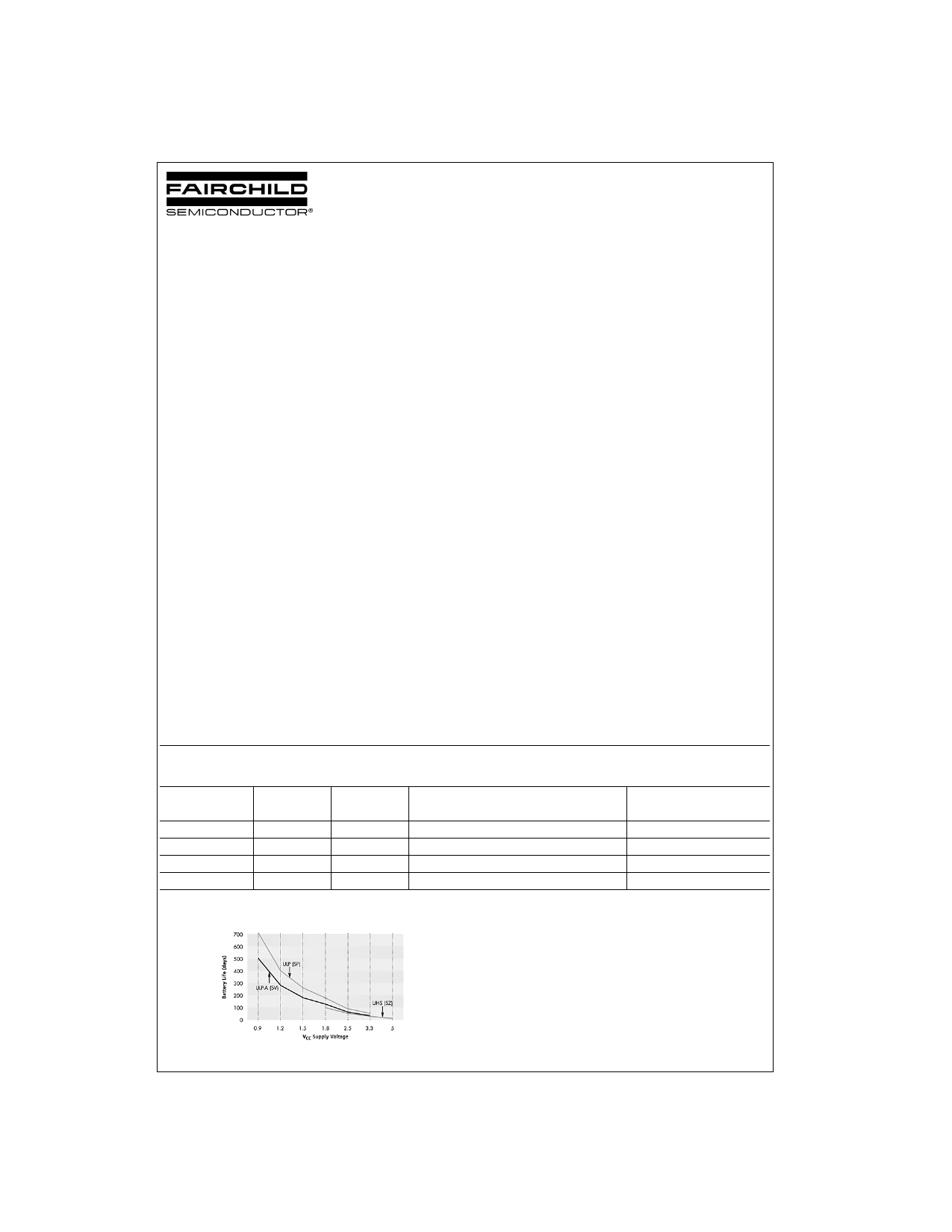
Battery Life vs. VCC Supply Voltage
TinyLogic ULP and ULP-A with up to 50% less power consumption can
extend your battery life significantly.
Battery Life = (Vbattery *Ibattery*.9)/(Pdevice)/24hrs/day
Where, Pdevice = (ICC * VCC) + (CPD + CL) * VCC2 * f
Assumes ideal 3.6V Lithium Ion battery with current rating of 900mAH and
derated 90% and device frequency at 10MHz, with CL = 15 pF load
TinyLogic, MicroPak, and Quiet Series are trademarks of Fairchild Semiconductor Corporation.
© 2003 Fairchild Semiconductor Corporation DS500671
www.fairchildsemi.com
1 page 
Absolute Maximum Ratings(Note 1)
Recommended Operating
Supply Voltage (VCC)
DC Input Voltage (VIN)
DC Output Voltage (VOUT)
HIGH or LOW State (Note 2)
VCC = 0V
DC Input Diode Current (IIK) VIN < 0V
DC Output Diode Current (IOK)
VOUT < 0V
VOUT > VCC
DC Output Source/Sink Current (IOH/IOL)
DC VCC or Ground Current per
Supply Pin (ICC or Ground)
Storage Temperature Range (TSTG)
−0.5V to +4.6V
−0.5V to +4.6V
−0.5V to VCC +0.5V
−0.5V to +4.6V
±50 mA
−50 mA
+50 mA
± 50 mA
± 50 mA
−65°C to +150°C
Conditions (Note 3)
Supply Voltage
Input Voltage (VIN)
Output Voltage (VOUT)
VCC = 0.0V
HIGH or LOW State
Output Current in IOH/IOL
VCC = 3.0V to 3.6V
VCC = 2.3V to 2.7V
VCC = 1.65V to 1.95V
VCC = 1.4V to 1.6V
VCC = 1.1V to 1.3V
VCC = 0.9V
Free Air Operating Temperature (TA)
Minimum Input Edge Rate (∆t/∆V)
0.9V to 3.6V
0V to 3.6V
0V to 3.6V
0V to VCC
±24 mA
±18 mA
±6 mA
±4 mA
±2 mA
±0.1 mA
−40°C to +85°C
VIN = 0.8V to 2.0V, VCC = 3.0V
10 ns/V
Note 1: Absolute Maximum Ratings: are those values beyond which the
safety of the device cannot be guaranteed. The device should not be oper-
ated at these limits. The parametric values defined in the Electrical Charac-
teristics tables are not guaranteed at the absolute maximum ratings. The
“Recommended Operating Conditions” table will define the conditions for
actual device operation.
Note 2: IO Absolute Maximum Rating must be observed.
Note 3: Unused inputs must be held HIGH or LOW. They may not float.
DC Electrical Characteristics
Symbol
Parameter
VP Positive Threshold Voltage
VN Negative Threshold Voltage
VH Hysteresis Voltage
VCC
(V)
0.90
1.10
1.40
1.65
2.30
2.70
0.90
1.10
1.40
1.65
2.30
2.70
0.90
1.10
1.40
1.65
2.30
2.70
TA = +25°C
Min Max
0.3 0.7
0.4 1.0
0.5 1.4
0.7 1.5
1.0 1.8
1.3 2.2
0.10
0.6
0.15
0.7
0.2 0.8
0.25
0.9
0.4 1.15
0.6 1.5
0.07
0.5
0.08
0.6
0.1 0.8
0.15
1.0
0.25
1.1
0.40
1.2
TA = −40°C to +85°C
Min Max
0.3 0.7
0.4 1.0
0.5 1.4
0.7 1.5
1.0 1.8
1.3 2.2
0.1 0.6
0.15
0.7
0.2 0.8
0.25
0.9
0.4 1.15
0.6 1.5
0.07
0.5
0.08
0.6
0.1 0.8
0.15
1.0
0.25
1.1
0.40
1.2
Units
V
V
V
Conditions
5 www.fairchildsemi.com
5 Page 
Physical Dimensions inches (millimeters) unless otherwise noted (Continued)
6-Lead MicroPak, 1.0mm Wide
Package Number MAC06A
Fairchild does not assume any responsibility for use of any circuitry described, no circuit patent licenses are implied and
Fairchild reserves the right at any time without notice to change said circuitry and specifications.
LIFE SUPPORT POLICY
FAIRCHILD’S PRODUCTS ARE NOT AUTHORIZED FOR USE AS CRITICAL COMPONENTS IN LIFE SUPPORT
DEVICES OR SYSTEMS WITHOUT THE EXPRESS WRITTEN APPROVAL OF THE PRESIDENT OF FAIRCHILD
SEMICONDUCTOR CORPORATION. As used herein:
1. Life support devices or systems are devices or systems
which, (a) are intended for surgical implant into the
body, or (b) support or sustain life, and (c) whose failure
to perform when properly used in accordance with
instructions for use provided in the labeling, can be rea-
sonably expected to result in a significant injury to the
user.
2. A critical component in any component of a life support
device or system whose failure to perform can be rea-
sonably expected to cause the failure of the life support
device or system, or to affect its safety or effectiveness.
www.fairchildsemi.com
11 www.fairchildsemi.com
11 Page | ||
| Páginas | Total 11 Páginas | |
| PDF Descargar | [ Datasheet NC7SV57P6X.PDF ] | |
Hoja de datos destacado
| Número de pieza | Descripción | Fabricantes |
| NC7SV57P6X | TinyLogic. ULP-A Universal Configurable 2-Input Logic Gates | Fairchild |
| Número de pieza | Descripción | Fabricantes |
| SLA6805M | High Voltage 3 phase Motor Driver IC. |
Sanken |
| SDC1742 | 12- and 14-Bit Hybrid Synchro / Resolver-to-Digital Converters. |
Analog Devices |
|
DataSheet.es es una pagina web que funciona como un repositorio de manuales o hoja de datos de muchos de los productos más populares, |
| DataSheet.es | 2020 | Privacy Policy | Contacto | Buscar |