|
|
|
PDF OPA660 Data sheet ( Hoja de datos )
| Número de pieza | OPA660 | |
| Descripción | Wide Bandwidth OPERATIONAL TRANSCONDUCTANCE AMPLIFIER AND BUFFER | |
| Fabricantes | Burr-Brown | |
| Logotipo | ||
Hay una vista previa y un enlace de descarga de OPA660 (archivo pdf) en la parte inferior de esta página. Total 18 Páginas | ||
|
No Preview Available !
® OPA660
OPA660
OPA660
Wide Bandwidth
OPERATIONAL TRANSCONDUCTANCE
AMPLIFIER AND BUFFER
FEATURES
APPLICATIONS
q WIDE BANDWIDTH: 850MHz
q HIGH SLEW RATE: 3000V/µs
q LOW DIFFERENTIAL GAIN/PHASE
ERROR: 0.06%/0.02°
q VERSATILE CIRCUIT FUNCTION
q EXTERNAL IQ-CONTROL
DESCRIPTION
The OPA660 is a versatile monolithic component
designed for wide-bandwidth systems including high
performance video, RF and IF circuitry. It includes a
wideband, bipolar integrated voltage-controlled cur-
rent source and voltage buffer amplifier.
The voltage-controlled current source or Operational
Transconductance Amplifier (OTA) can be viewed as
an “ideal transistor.” Like a transistor, it has three
terminals—a high-impedance input (base), a low-
impedance input/output (emitter), and the current
output (collector). The OTA, however, is self-biased
and bipolar. The output current is zero-for-zero dif-
ferential input voltage. AC inputs centered about zero
produce an output current which is bipolar and cen-
tered about zero. The transconductance of the OTA
can be adjusted with an external resistor, allowing
bandwidth, quiescent current and gain trade-offs to
be optimized.
The open-loop buffer amplifier provides 850MHz
bandwidth and 3000V/µs slew rate. Used as a basic
building block, the OPA660 simplifies the design of
AGC amplifiers, LED driver circuits for Fiber Optic
Transmission, integrators for fast pulses, fast control
loop amplifiers, and control amplifiers for capacitive
sensors and active filters.
The OPA660 is packaged in SO-8 surface-mount,
and 8-pin plastic DIP, specified from –40°C to +85°C.
q BASE LINE RESTORE CIRCUITS
q VIDEO/BROADCAST EQUIPMENT
q COMMUNICATIONS EQUIPMENT
q HIGH-SPEED DATA ACQUISITION
q WIDEBAND LED DRIVER
q AGC-MULTIPLIER
q NS-PULSE INTEGRATOR
q CONTROL LOOP AMPLIFIER
q 400MHz DIFFERENTIAL INPUT
AMPLIFIER
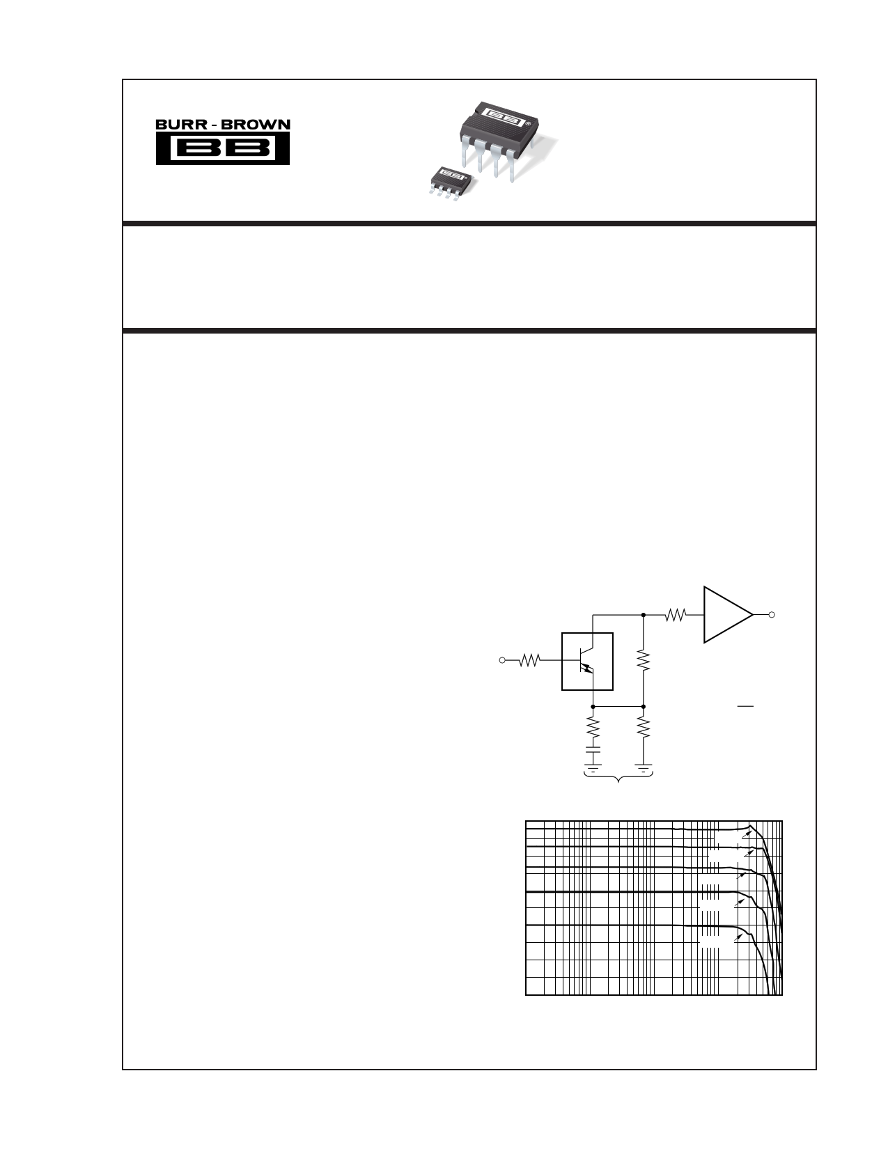
8
C
VI 100Ω 3 B OTA
R1
E
2
RP
82Ω
CP
6.4pF
200Ω 5
+1
6
VO
R3
390Ω
R5
100Ω
IQ = 20mA
G = 1 + R3 = 3
2R5
XE
OPA660 DIRECT-FEEDBACK FREQUENCY RESPONSE
20
15 5Vp-p
10 2.8Vp-p
5 1.4Vp-p
0
–5 0.6Vp-p
–10
–15 0.2Vp-p
–20
–25
–30
100k
1M
10M
100M
Frequency (Hz)
1G
International Airport Industrial Park • Mailing Address: PO Box 11400, Tucson, AZ 85734 • Street Address: 6730 S. Tucson Blvd., Tucson, AZ 85706 • Tel: (520) 746-1111 • Twx: 910-952-1111
Internet: http://www.burr-brown.com/ • FAXLine: (800) 548-6133 (US/Canada Only) • Cable: BBRCORP • Telex: 066-6491 • FAX: (520) 889-1510 • Immediate Product Info: (800) 548-6132
© 1990 Burr-Brown Corporation
PDS-1072F
Printed in U.S.A. April, 1995
1 page 
TYPICAL PERFORMANCE CURVES (CONT)
IQ = 20mA, TA = +25°C, and VS = ±5V unless otherwise noted.
BUFFER AND OTA B-INPUT OFFSET VOLTAGE
vs TEMPERATURE
20
15
10
5
0
–5
–10
–15
–20
–25
0 25 50 75
Temperature (°C)
100
BUFFER AND OTA B-INPUT RESISTANCE
vs TOTAL QUIESCENT CURRENT (IQ)
4
RINOTA
3
RINBUF
2
1
0
–1
4
6 8 10 12 14 16 18
Total Quiescent Current — IQ (mA)
20
BUFFER OUTPUT AND OTA E-OUTPUT RESISTANCE
vs TOTAL QUIESCENT CURRENT (IQ)
40
30
20
10 ROUTBUF
ROUTOTA
0
4 6 8 10 12 14 16 18 20
Total Quiescent Current—IQ (mA)
4000
BUFFER SLEW RATE
vs TOTAL QUIESCENT CURRENT (IQ)
3800
3600
3400 Rising Edge
3200
3000
2800
2600
Falling Edge
2400
2200
2000
4 6 8 10 12 14 16 18 20
Total Quiescent Current—IQ (mA)
OTA TRANSCONDUCTANCE
vs TOTAL QUIESCENT CURRENT (IQ)
150
100
50
0
0 2 4 6 8 10 12 14 16 18 20
Total Quiescent Current—IQ (mA)
1000
100
OTA TRANSCONDUCTANCE vs FREQUENCY
RL = 50Ω
IQ = 20mA 106mA/V
IQ = 10mA 66mA/V
10
1M
IQ = 5mA 40mA/V
10M 100M
Frequency (Hz)
1G
®
5 OPA660
5 Page 
A positive voltage at the B, pin 3, causes a positive current
to flow out of the C, pin 8. Figure 5b shows an amplifier
connection of the OTA, the equivalent of a common-emitter
transistor amplifier. Input and output can be ground-refer-
enced without any biasing. Due to the sense of the output
current, the amplifier is non-inverting. Figure 8 shows the
amplifier with various gains and output voltages using this
configuration.
Just as transistor circuits often use emitter degeneration,
OTA circuits may also use degeneration. This can be used to
reduce the effect that offset voltage and offset current might
otherwise have on the DC operating point of the OTA. The
E-degeneration resistor may be bypassed with a large ca-
pacitor to maintain high AC gain. Other circumstances may
suggest a smaller value capacitor used to extend or optimize
high-frequency performance.
The transconductance of the OTA with degeneration can be
calculated by—
1
gm =
1
gm
+ RE
Figure 6b shows the OTA connected as an E-follower—a
voltage buffer. The buffer formed by this connection per-
forms virtually the same as the buffer section of the OPA660
(the actual signal path is identical).
It is recommended to use a low value resistor in series with
the B OTA and buffer inputs. This reduces any tendency to
oscillate and controls frequency response peaking. Values
from 25Ω to 200Ω are typical.
Figure 7 shows the Common-B amplifier. This configura-
tion produces an inverting gain, and a low impedance input.
This low impedance can be converted to a high impedance
by inserting the buffer amplifier in series.
CIRCUIT LAYOUT
The high frequency performance of the OPA660 can be
greatly affected by the physical layout of the circuit. The
following tips are offered as suggestions, not dogma.
• Bypass power supplies very close to the device pins. Use
a combination between tantalum capacitors (approxi-
mately 2.2µF) and polyester capacitors. Surface-mount
types are best because they provide lowest inductance.
• Make short, wide interconnection traces to minimize
series inductance.
• Use a large ground plane to assure that a low impedance
ground is available throughout the layout.
• Do not extend the ground plane under high impedance
nodes sensitive to stray capacitance.
• Sockets are not recommended because they add signifi-
cant inductance.
VO
3
100Ω
R1
VI
RL1
8
OTA
RL2
Network
Analyzer
RIN
50Ω
rE
RL = RL1 + RL2 || RIN
2
RE
G = RL
RE + rE
, rE
=
1
gm
At IQ = 20mA
rE
=
1
125mA/V
= 8Ω
G
=
RL
RE + 8Ω
at
IQ
=
20mA
20
15
10
5
0
–5
–10
–15
–20
–25
–30
300k
1M
2.8Vp-p
–3dB Point
1.4Vp-p
600mVp-p
200mVp-p
10M 100M
Frequency (Hz)
1G 3G
IQ = 20mA R1 = 100Ω RE = 51Ω RL = 100Ω Gain = 2
FIGURE 8. Common-E Amplifier Performance.
11
20
15
10 2.8Vp-p
–3dB Point
5 1.4Vp-p
0
600mVp-p
–5
–10
–15 200mVp-p
–20
–25
–30
300k 1M
10M
100M
Frequency (Hz)
1G 3G
IQ = 20mA R1 = 100Ω RE = 51Ω RL = 50Ω Gain = 1
20
15
10
5
0
–5
–10
–15
–20
–25
–30
100k
5Vp-p
2.8Vp-p
1.4Vp-p
–3dB Point
600mVp-p
200mVp-p
1M 10M 100M
Frequency (Hz)
1G
IQ = 20mA R1 = 100Ω RE = 51Ω RL = 500Ω Gain = 10
OPA660
®
11 Page | ||
| Páginas | Total 18 Páginas | |
| PDF Descargar | [ Datasheet OPA660.PDF ] | |
Hoja de datos destacado
| Número de pieza | Descripción | Fabricantes |
| OPA660 | Wide Bandwidth Operational Transconductance Amp and Buffer | Texas Instruments |
| OPA660 | Wide Bandwidth OPERATIONAL TRANSCONDUCTANCE AMPLIFIER AND BUFFER | Burr-Brown |
| Número de pieza | Descripción | Fabricantes |
| SLA6805M | High Voltage 3 phase Motor Driver IC. |
Sanken |
| SDC1742 | 12- and 14-Bit Hybrid Synchro / Resolver-to-Digital Converters. |
Analog Devices |
|
DataSheet.es es una pagina web que funciona como un repositorio de manuales o hoja de datos de muchos de los productos más populares, |
| DataSheet.es | 2020 | Privacy Policy | Contacto | Buscar |