|
|
|
PDF CA3240 Data sheet ( Hoja de datos )
| Número de pieza | CA3240 | |
| Descripción | BiMOS Operational Amplifier | |
| Fabricantes | Intersil | |
| Logotipo | ||
Hay una vista previa y un enlace de descarga de CA3240 (archivo pdf) en la parte inferior de esta página. Total 15 Páginas | ||
|
No Preview Available !
®
Data Sheet
CA3240, CA3240A
March 4, 2005
FN1050.6
Dual, 4.5MHz, BiMOS Operational Amplifier
with MOSFET Input/Bipolar Output
The CA3240A and CA3240 are dual versions of the popular
CA3140 series integrated circuit operational amplifiers. They
combine the advantages of MOS and bipolar transistors on
the same monolithic chip. The gate-protected MOSFET
(PMOS) input transistors provide high input impedance and
a wide common-mode input voltage range (typically to 0.5V
below the negative supply rail). The bipolar output
transistors allow a wide output voltage swing and provide a
high output current capability.
The CA3240A and CA3240 are compatible with the industry
standard 1458 operational amplifiers in similar packages.
Ordering Information
TEMP.
PART NUMBER RANGE (oC)
PACKAGE
PKG.
DWG. #
CA3240AE
-40 to 85 8 Ld PDIP
E8.3
CA3240AEZ
(See Note)
-40 to 85 8 Ld PDIP
(Pb-free)
E8.3
CA3240E
-40 to 85 8 Ld PDIP
E8.3
CA3240EZ
(See Note)
-40 to 85 8 Ld PDIP
(Pb-free)
E8.3
Pb-free PDIPs can be used for through hole wave solder processing only.
They are not intended for use in Reflow solder processing applications.
NOTE: Intersil Pb-free products employ special Pb-free material sets;
molding compounds/die attach materials and 100% matte tin plate termination
finish, which are RoHS compliant and compatible with both SnPb and Pb-free
soldering operations. Intersil Pb-free products are MSL classified at Pb-free
peak reflow temperatures that meet or exceed the Pb-free requirements of
IPC/JEDEC J STD-020.
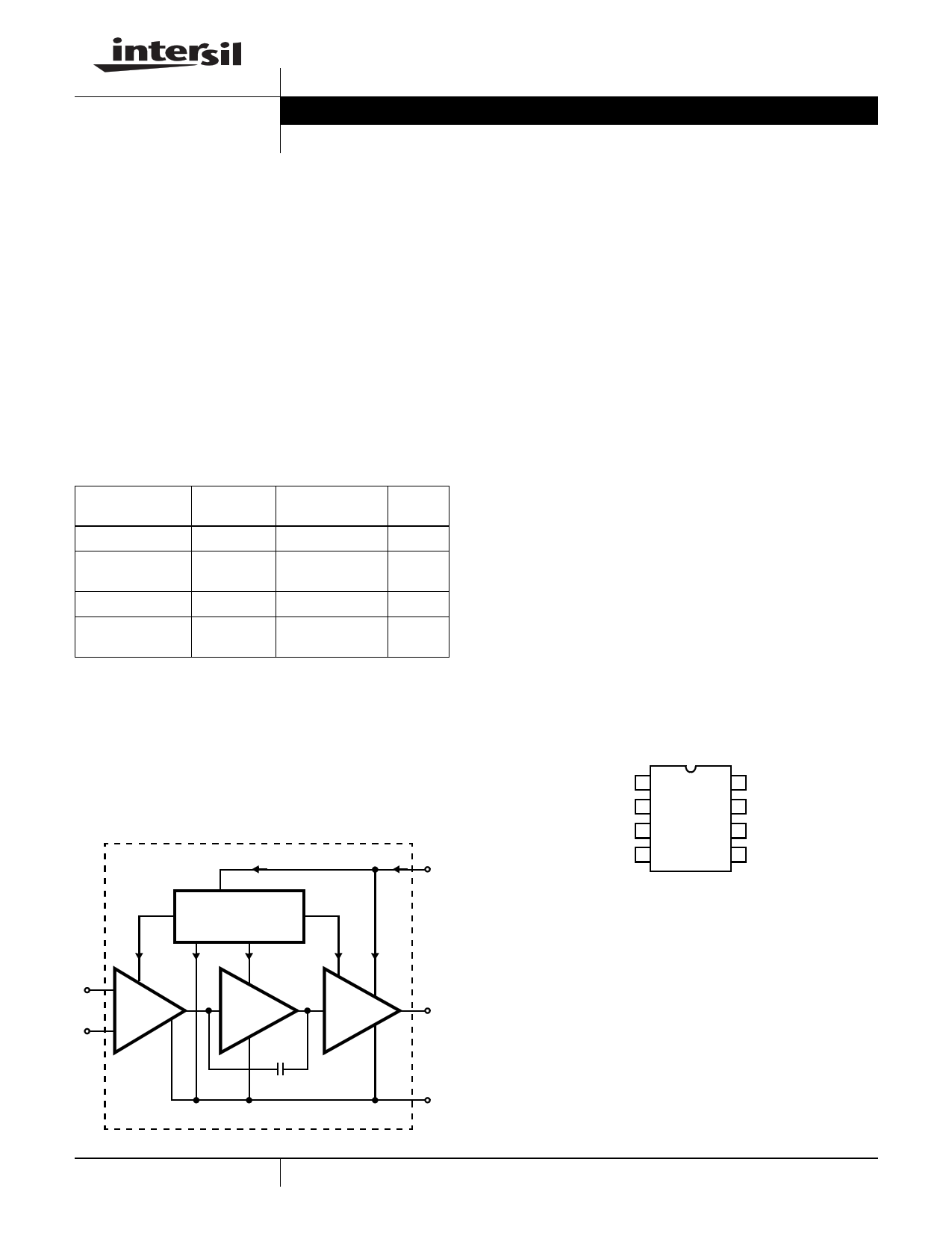
Functional Diagram
2mA
+
IN-
PUT
-
BIAS CIRCUIT
CURRENT SOURCES
AND REGULATOR
200μA 1.6mA 200μA
A ≈ 10
A ≈ 10,000
C1
12pF
4mA V+
2μA 2mA
A≈1
OUT-
PUT
V-
Features
• Dual Version of CA3140
• Internally Compensated
• MOSFET Input Stage
- Very High Input Impedance (ZIN) 1.5TΩ (Typ)
- Very Low Input Current (II) 10pA (Typ) at ±15V
- Wide Common-Mode Input Voltage Range (VICR): Can
Be Swung 0.5V Below Negative Supply Voltage Rail
• Directly Replaces Industry Type 741 in Most Applications
• Pb-Free Available (RoHS Compliant)
Applications
• Ground Referenced Single Amplifiers in Automobile and
Portable Instrumentation
• Sample and Hold Amplifiers
• Long Duration Timers/Multivibrators (Microseconds-
Minutes-Hours)
• Photocurrent Instrumentation
• Intrusion Alarm System
• Active Filters
• Comparators
• Function Generators
• Instrumentation Amplifiers • Power Supplies
Pinout
CA3240, CA3240A (PDIP)
TOP VIEW
OUTPUT (A)
INV.
INPUT (A)
NON-INV.
INPUT (A)
V-
1
2
3
4
8 V+
7 OUTPUT
INV.
6 INPUT (B)
5 NON-INV.
INPUT (B)
1 CAUTION: These devices are sensitive to electrostatic discharge; follow proper IC Handling Procedures.
1-888-INTERSIL or 1-888-352-6832 | Intersil (and design) is a registered trademark of Intersil Americas Inc.
Copyright Intersil Americas Inc. 2001-2005. All Rights Reserved
All other trademarks mentioned are the property of their respective owners.
1 page 
CA3240, CA3240A
Test Circuits and Waveforms (Continued)
+15V
RS
1MΩ
+
CA3240
-
-15V
0.01μF
NOISE
VOLTAGE
OUTPUT
30.1kΩ
0.01μF
BW (-3dB) = 140kHz
TOTAL NOISE VOLTAGE
(REFERRED TO INPUT) = 48μV (TYP)
1kΩ
FIGURE 2. TEST CIRCUIT AMPLIFIER (30dB GAIN) USED FOR WIDEBAND NOISE MEASUREMENT
Schematic Diagram (One Amplifier of Two)
BIAS CIRCUIT
Q1
Q7
R1
8K
D1
Q6
Q8
D2
INVERTING
INPUT
-
NON-INVERTING
INPUT +
INPUT STAGE
Q2
Q5
D3 D4
D5
SECOND STAGE OUTPUT STAGE
D7
R9
Q3 50Ω
R10
Q19 1K
Q4
R11
20Ω
Q17
R8
1K
Q18
DYNAMIC CURRENT SINK
V+
Q20
R12
12K
R13
15K
D8
R14
20K
Q21
OUTPUT
Q9 Q10
R2
500Ω
Q11
R3
500Ω
Q12
R4
500Ω
R5
500Ω
C1
12pF
Q13
Q14 Q15 Q16
R6
50Ω
D6
R7
30Ω
NOTES:
9. All resistance values are in ohms.
V-
5 FN1050.6
March 4, 2005
5 Page 
CA3240, CA3240A
C30809
PHOTO
DIODE
C30809
PHOTO
DIODE
0.015μF
100K
+15V
8 +15V
+15V
2-
1/2
CA3240E
1
2K
7
5.1K
1.3
3
+
200K
3
+
CA3140
6
K
5+
-
2
13K 1/2
2K
CA3240E
7
4
6-
4
-15V
-15V
100K
200k
0.015μF
FIGURE 11. DIFFERENTIAL LIGHT DETECTOR
OUTPUT
Differential Light Detector
In the circuit shown in Figure 11, the CA3240E converts the
current from two photo diodes to voltage, and applies 1V of
reverse bias to the diodes. The voltages from the CA3240E
outputs are subtracted in the second stage (CA3140) so that
only the difference is amplified. In this manner, the circuit
can be used over a wide range of ambient light conditions
without circuit component adjustment. Also, when used with
a light source, the circuit will not be sensitive to changes in
light level as the source ages.
11 FN1050.6
March 4, 2005
11 Page | ||
| Páginas | Total 15 Páginas | |
| PDF Descargar | [ Datasheet CA3240.PDF ] | |
Hoja de datos destacado
| Número de pieza | Descripción | Fabricantes |
| CA324 | Operational Amplifiers | Intersil |
| CA3240 | BiMOS Operational Amplifier | Intersil |
| CA3240 | BiMOS Operational Amplifier with MOSFET Input/Bipolar Output | Harris |
| CA3240A | BiMOS Operational Amplifier | Intersil |
| Número de pieza | Descripción | Fabricantes |
| SLA6805M | High Voltage 3 phase Motor Driver IC. |
Sanken |
| SDC1742 | 12- and 14-Bit Hybrid Synchro / Resolver-to-Digital Converters. |
Analog Devices |
|
DataSheet.es es una pagina web que funciona como un repositorio de manuales o hoja de datos de muchos de los productos más populares, |
| DataSheet.es | 2020 | Privacy Policy | Contacto | Buscar |