|
|
|
PDF SA9904B Data sheet ( Hoja de datos )
| Número de pieza | SA9904B | |
| Descripción | Three Phase Power / Energy IC with SPI Interface | |
| Fabricantes | ETC | |
| Logotipo | ||
Hay una vista previa y un enlace de descarga de SA9904B (archivo pdf) en la parte inferior de esta página. Total 12 Páginas | ||
|
No Preview Available !
Three Phase Power / Energy IC with SPI
Interface
SA9904B
sames
FEATURES
+ Bi-directional active and reactive power/energy
measurement
+ RMS Voltage and frequency measurement
+ Individual Phase information
+ SPI communication bus
+ Meets the IEC 61036 Specification requirements for Class 1
AC Watt hour meters
+ Meets the IEC 61268 Specification requirements for
Class 2 VAR hour meters
+ Protected against ESD
+ Total power consumption rating below 60mW
+ Uses current transformers for current sensing
+ Operates over a wide temperature range
+ Precision on-chip voltage reference
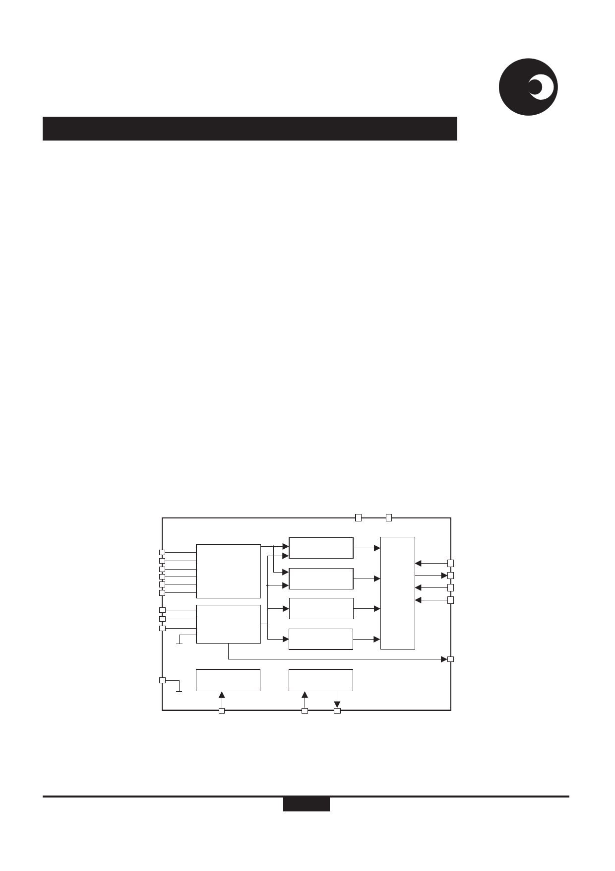
DESCRIPTION
The SAMES SA9904B is a three phase bi-directional
energy/power metering integrated circuit that has been
designed to measure active and reactive energy, RMS mains
voltage and frequency. The SA9904B has an integrated SPI
serial interface for communication with a micro-controller.
Measured values for active and reactive energy, the mains
voltage and frequency for each phase are accessible through
the SPI interface from 24 bit registers. The SA9904B active and
reactive energy registers are capable of holding at least 52
seconds of accumulated energy at full load. A mains voltage
zero crossover is available on the F50 output.
The SA9904B includes all the required functions for three-
phase power and energy measurement such as oversampling
A/D converters for the voltage and current sense inputs, power
calculation and energy integration. This innovative universal
three phase power/energy metering integrated circuit is ideally
suited for energy calculations in applications such as electricity
dispensing systems, residential metering and factory energy
metering and control.
The SA9904B integrated circuit is available in 20 pin dual-in-
line plastic (PDIP20), as well as 20 pin small outline (SOIC20)
package types.
VDD VSS
IIP1
IIN2
IIP2
IIN2
IIP3
IIN3
IVP1
IVP2
IVP3
CURRENT
ADC
VOLTAGE
ADC
ACTIVE
REACTIVE
RMS
VOLTAGE
MAINS
FREQ.
GND
VOLTAGE
REF.
OSC
DR-01641
VREF
OSC1 OSC2
Figure 1: Block diagram
SPI
SPEC-0447 (REV. 6)
1/12
DI
DO
SCK
CS
F50
04-07-03
1 page 
SA9904B
sames
Where:
IL = Line current or if a CT is used IL = Line current / CT ratio
Rsh = Shunt resistor or CT termination resistor.
Rsh should be less than the resistance of the CT's secondary
winding.
Voltage Sense Input (IVP1, IVP2, IVP3)
Figure 6 shows the voltage sense (IVP) input configuration for
one phase. The exact circuit is duplicated for the other two
phases. The current into the voltage sense inputs (virtual
ground) should be set to 14µARMS at rated voltage conditions.
The voltage sense inputs saturate at an input current of ±25µA
peak.
Ch1 Voltage
R16 R19 R22
14VRMS
C5 R8 14µARMS
IVP1
Neutral
Dr-01645
GND
R13
GND
Figure 6: Voltage sense input configuration
The individual mains voltages are divided down to 14VRMS per
phase. The resistor R8 sets the current for the voltage sense
input. The voltage divider is calculated for a voltage drop of 14V.
With a phase voltage of 230V the equation for the voltage divider
is:
RA = R16 + R19 + R22
RB = R8 || R13
Combining the two equations gives:
(RA + RB) / 230V = RB / 14V
A 24K resistor is chosen for R13 and a 1M resistor for R8.
Substituting these values results in:
RB = 23.44K
RA = RB x (230V / 14V-1)
RA = 361.6K
Resistor values for R16, R19 and R22 is chosen to be 120K
each.
The capacitor C5 is used to compensate for any phase shift
between the voltage sense and current sense input caused by
the current transformer. As an example to compensate for a
phase shift of 0.18 degrees the capacitor value is calculated as
follows:
C = 1 / (2 x p x Mains frequency x R5 x tan (Phase shift angle))
C = 1 / (2 x p x 50Hz x 1MW x tan (0.18 degrees))
C = 1.013µF
Reference Voltage (VREF)
The VREF pin is the reference for the bias resistor. With a bias
resistor of 47kW connected to Vss optimum conditions are set.
Serial Clock (SCK)
The SCK pin is used to synchronize data interchange between
the micro controller and the SA9904B. The clock signal on this
pin is generated by the micro controller and determines the
data transfer rate of the DO and DI pins.
Serial Data In (DI)
The DI pin is the serial data input pin for the SA9904B. Data will
be input at a rate determined by the Serial Clock (SCK). Data
will be accepted only during an active chip select (CS).
Chip Select (CS)
The CS input is used to address the SA9904B. An active high
on this pin enables the SA9904B to initiate data exchange.
OUTPUT SIGNALS
Serial Data Out (DO)
The DO pin is the serial data output pin for the SA9904B. The
Serial Clock (SCK) determines the data output rate. Data is
only transferred during on active chip select (CS). This output
is tri-state when CS is low.
Mains Voltage sense zero crossover (F50)
The F50 output generates a signal, which follows the mains
voltage zero crossings, see figure 7. This output generates a
pulse on the rising edge of the mains voltage zero crossing
point. Internal logic ensures that this signal is generated from a
valid phase. Should all three phase be missing but power still
applied to the SA9904B this output will generate a constant
54Hz signal. The micro controller can use the F50 to extract
mains timing.
Phase Voltage
F50
Dr-01646
1ms to 2ms
+5V
0V (Vss)
1ms to 2ms
Figure 7: Mains voltage zero crossover
SPI - INTERFACE
Description
A serial peripheral interface bus (SPI) is a synchronous bus
used for data transfers between a micro controller and the
SA9904B. The pins DO (Serial Data Out), DI (Serial Data In),
CS (Chip Select), and SCK (Serial Clock) are used in the bus
implementation. The SA9904B is the slave device with the
micro controller being bus master. The CS input initiates and
terminates data transfers. A SCK signal (generated by the
micro controller) strobes data between the micro-controller
http://www.sames.co.za
5/12
5 Page 
SA9904B
sames
Parts List for Application Circuit: Figure 11
Symbol
U1
R1
R2
R3
R4
R5
R6
R7
R8
R9
R10
R11
R12
R13
R14
R15
R16
R17
R18
R19
R20
R21
R22
R23
R24
R25
R26
R27
C1
C2
C3
C4
C5
C6
CT1
CT2
CT3
X1
Description
SA9904B
Resistor, 2.7k, 1/4W, 1% metal
Resistor, 2.7k, 1/4W, 1% metal
Resistor, 2.7k, 1/4W, 1% metal
Resistor, 2.7k, 1/4W, 1% metal
Resistor, 2.7k, 1/4W, 1% metal
Resistor, 2.7k, 1/4W, 1% metal
Resistor, 47k, 1/4W, 1%, metal
Resistor, 1M, 1/4W, 1%, metal
Resistor, 1M, 1/4W, 1%, metal
Resistor, 1M, 1/4W, 1%, metal
Resistor, 24k, 1/4W, 1%, metal
Resistor, 24k, 1/4W, 1%, metal
Resistor, 24k, 1/4W, 1%, metal
Resistor, 120k, 1/4W, 1%, metal
Resistor, 120k, 1/4W, 1%, metal
Resistor, 120k, 1/4W, 1%, metal
Resistor, 120k, 1/4W, 1%, metal
Resistor, 120k, 1/4W, 1%, metal
Resistor, 120k, 1/4W, 1%, metal
Resistor, 120k, 1/4W, 1%, metal
Resistor, 120k, 1/4W, 1%, metal
Resistor, 120k, 1/4W, 1%, metal
Resistor, 1k, 1/4W, 1%, metal
Resistor, 1k, 1/4W, 1%, metal
Resistor, 2.7R, 1/4W, 1%, metal
Resistor, 2.7R, 1/4W, 1%, metal
Resistor, 2.7R, 1/4W, 1%, metal
Capacitor, 220nF
Capacitor, 220nF
Capacitor, 820nF
Capacitor, 820nF
Capacitor, 820nF
Capacitor, 820nF
Current Transformer, TZ76
Current Transformer, TZ76
Current Transformer, TZ76
Crystal, 3.57954MHz
Detail
PDIP20 / SOIC20
Note 1
Note 1
Note 1
Note 1
Note 1
Note 1
Note 1
Note 1
Note 1
Note 2
Note 2
Note 2
Note 3
Note 1: Resistor (R1 to R6) values are dependant on the selection of the termination resistors (R25 to R27) and CT combination.
Note 2: Capacitor values may be selected to compensate for phase errors caused by the current transformers.
Note 3: Capacitor C6 to be positioned as close as possible to supply pins VDD and VSS of U1.
http://www.sames.co.za
11/12
11 Page | ||
| Páginas | Total 12 Páginas | |
| PDF Descargar | [ Datasheet SA9904B.PDF ] | |
Hoja de datos destacado
| Número de pieza | Descripción | Fabricantes |
| SA9904B | Three Phase Power / Energy IC with SPI Interface | ETC |
| Número de pieza | Descripción | Fabricantes |
| SLA6805M | High Voltage 3 phase Motor Driver IC. |
Sanken |
| SDC1742 | 12- and 14-Bit Hybrid Synchro / Resolver-to-Digital Converters. |
Analog Devices |
|
DataSheet.es es una pagina web que funciona como un repositorio de manuales o hoja de datos de muchos de los productos más populares, |
| DataSheet.es | 2020 | Privacy Policy | Contacto | Buscar |