|
|
|
PDF HA1-5320-5 Data sheet ( Hoja de datos )
| Número de pieza | HA1-5320-5 | |
| Descripción | 1 Microsecond Precision Sample and Hold Amplifier | |
| Fabricantes | Intersil Corporation | |
| Logotipo | ||
Hay una vista previa y un enlace de descarga de HA1-5320-5 (archivo pdf) en la parte inferior de esta página. Total 7 Páginas | ||
|
No Preview Available !
Data Sheet
HA-5320
April 1999 File Number 2857.4
1 Microsecond Precision Sample and
Hold Amplifier
The HA-5320 was designed for use in precision, high speed
data acquisition systems.
The circuit consists of an input transconductance amplifier
capable of providing large amounts of charging current, a low
leakage analog switch, and an output integrating amplifier. The
analog switch sees virtual ground as its load; therefore, charge
injection on the hold capacitor is constant over the entire
input/output voltage range. The pedestal voltage resulting from
this charge injection can be adjusted to zero by use of the offset
adjust inputs. The device includes a hold capacitor. However, if
improved droop rate is required at the expense of acquisition
time, additional hold capacitance may be added externally.
This monolithic device is manufactured using the Intersil
Dielectric Isolation Process, minimizing stray capacitance
and eliminating SCRs. This allows higher speed and latch-
free operation. For further information, please see
Application Note AN538.
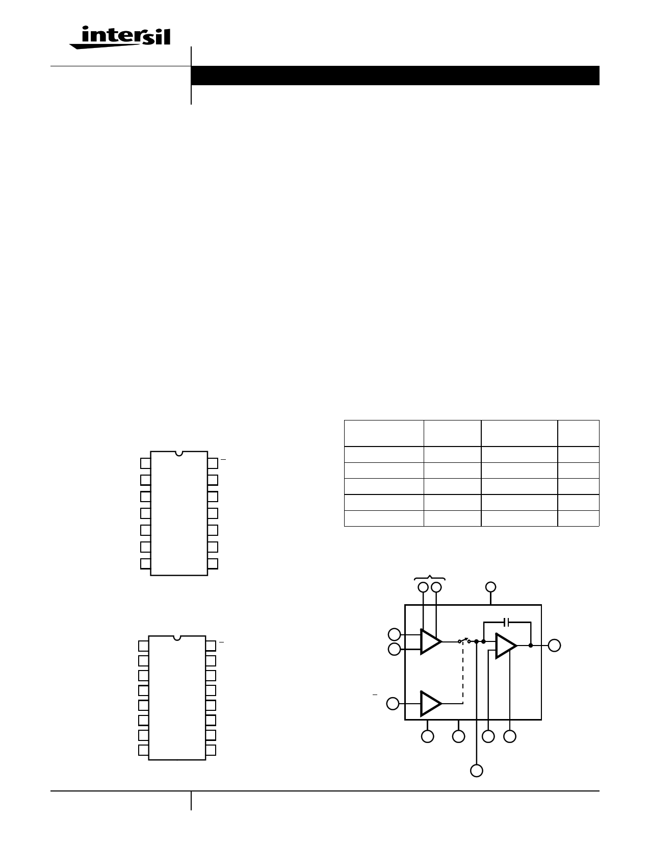
Pinouts
HA-5320
(PDIP, CERDIP)
TOP VIEW
-INPUT 1
+INPUT 2
OFFSET ADJUST 3
OFFSET ADJUST 4
V- 5
SIG. GND 6
OUTPUT 7
14 S/H CONTROL
13 SUPPLY GND
12 NC
11 CEXT
10 NC
9 V+
8
INTEGRATOR
BANDWIDTH
HA-5320
(SOIC)
TOP VIEW
-INPUT 1
+INPUT 2
OFFSET ADJUST 3
OFFSET ADJUST 4
V- 5
SIG. GND 6
OUTPUT 7
NC 8
16 S/H CONTROL
15 SUPPLY GND
14 NC
13 CEXT
12 NC
11 V+
10
INTEGRATOR
BANDWIDTH
9 NC
Features
• Gain, DC. . . . . . . . . . . . . . . . . . . . . . . . . . . . . 2 x 10⁶ V/V
• Acquisition Time . . . . . . . . . . . . . . . . . . . . . 1.0µs (0.01%)
• Droop Rate . . . . . . . . . . . . . . . . . . . . . . 0.08µV/µs (25oC)
17µV/µs (Full Temperature)
• Aperture Time . . . . . . . . . . . . . . . . . . . . . . . . . . . . . 25ns
• Hold Step Error (See Glossary) . . . . . . . . . . . . . . . . . 5mV
• Internal Hold Capacitor
• Fully Differential Input
• TTL Compatible
Applications
• Precision Data Acquisition Systems
• Digital to Analog Converter Deglitcher
• Auto Zero Circuits
• Peak Detector
Ordering Information
PART NUMBER
HA1-5320-2
HA1-5320-5
HA3-5320-5
HA9P5320-5
HA9P5320-9
TEMP.
RANGE (oC)
PACKAGE
-55 to 25 14 Ld CERDIP
0 to 75 14 Ld CERDIP
0 to 75 14 Ld PDIP
0 to 75 16 Ld SOIC
-40 to 85 16 Ld SOIC
Functional Diagram
OFFSET
ADJUST
34
V+
9
PKG.
NO.
F14.3
F14.3
E14.3
M16.3
M16.3
-INPUT 1
+INPUT 2
HA-5320
100pF
-
+
7 OUTPUT
S/H
CONTROL
14
13
SUPPLY
GND
5
6
8
INTEGRATOR
BANDWIDTH
V- SIG.
GND
11 CEXT
1 CAUTION: These devices are sensitive to electrostatic discharge; follow proper IC Handling Procedures.
1-888-INTERSIL or 321-724-7143 | Copyright © Intersil Corporation 1999
1 page 
HA-5320
The hold capacitor terminal (pin 11) remains at virtual
ground potential. Any PC connection to this terminal should
be kept short and “guarded” by the ground plane, since
nearby signal lines or power supply voltages will introduce
errors due to drift current.
Typical Application
Figure 5 shows the HA-5320 connected as a unity gain
noninverting amplifier - its most widely used configuration.
As an input device for a fast successive - approximation A/D
converter, it offers very high throughput rate for a monolithic
IC sample/hold amplifier. Also, the HA-5320’s hold step error
is adjustable to zero using the Offset Adjust potentiometer,
to deliver a 12-bit accurate output from the converter.
The application may call for an external hold capacitor CEXT as
shown. As mentioned earlier, 0.1CEXT is then recommended at
pin 8 to reduce output noise in the Hold mode.
The HA-5320 output circuit does not include short circuit
protection, and consequently its output impedance remains
low at high frequencies. Thus, the step changes in load
current which occur during an A/D conversion are absorbed
at the S/H output with minimum voltage error. A momentary
short circuit to ground is permissible, but the output is not
designed to tolerate a short of indefinite duration.
Glossary of Terms
Acquisition Time
The time required following a “sample” command, for the
output to reach its final value within ±0.1% or ±0.01%. This is
the minimum sample time required to obtain a given accuracy,
and includes switch delay time, slewing time and settling time.
Charge Transfer
The small charge transferred to the holding capacitor from
the inter-electrode capacitance of the switch when the unit is
switched to the HOLD mode. Charge transfer is directly
proportional to sample-to-hold offset pedestal error, where:
Charge Transfer (pC) = CH (pF) x Hold Step Error (V)
OFFSET
ADJUST
±15mV
10kΩ
-15V +15V
3 4 5 9 11 CEXT
Aperture Time
The time required for the sample-and-hold switch to open,
independent of delays through the switch driver and input
amplifier circuitry. The switch opening time is the interval
between the conditions of 10% open and 90% open.
Hold Step Error
Hold Step Error is the output error due to Charge Transfer (see
above). It may be calculated from the specified parameter,
Charge Transfer, using the following relationship:
Hold Step (V) = H--C---o-h--l--da---r--Cg---e-a---p-T---a-r--ca---in-t--a-s--n-f-e--c--r-e--(--p-(--p-C--F--)--)
See Performance Curves.
Effective Aperture Delay Time (EADT)
The difference between the digital delay time from the Hold
command to the opening of the S/H switch, and the
propagation time from the analog input to the switch.
EADT may be positive, negative or zero. If zero, the S/H
amplifier will output a voltage equal to VIN at the instant the
Hold command was received. For negative EADT, the output in
Hold (exclusive of pedestal and droop errors) will correspond to
a value of VIN that occurred before the Hold command.
Aperture Uncertainty
The range of variation in Effective Aperture Delay Time.
Aperture Uncertainty (also called Aperture Delay Uncertainty,
Aperture Time Jitter, etc.) sets a limit on the accuracy with
which a waveform can be reconstructed from sample data.
Drift Current
The net leakage current from the hold capacitor during the
hold mode. Drift current can be calculated from the droop
rate using the formula:
ID (pA) = CH(pF) × ∆--∆---V-t- (V/s)
HI-574A
VIN
S/H CONTROL
H
S
1
+
2
-
14
HA-5320
100pF
-
+
7 13
INPUT
CONVERT
13 6 8
0.1CEXT
SYSTEM POWER SYSTEM SIGNAL
GROUND
GROUND
5
R/C
9 ANALOG
COMMON
DIGITAL
OUTPUT
NOTE: Pin Numbers Refer to
DIP Package Only.
FIGURE 5. TYPICAL HA-5320 CONNECTIONS; NONINVERTING UNITY GAIN MODE
5
5 Page | ||
| Páginas | Total 7 Páginas | |
| PDF Descargar | [ Datasheet HA1-5320-5.PDF ] | |
Hoja de datos destacado
| Número de pieza | Descripción | Fabricantes |
| HA1-5320-2 | 1 Microsecond Precision Sample and Hold Amplifier | Intersil Corporation |
| HA1-5320-5 | 1 Microsecond Precision Sample and Hold Amplifier | Intersil Corporation |
| Número de pieza | Descripción | Fabricantes |
| SLA6805M | High Voltage 3 phase Motor Driver IC. |
Sanken |
| SDC1742 | 12- and 14-Bit Hybrid Synchro / Resolver-to-Digital Converters. |
Analog Devices |
|
DataSheet.es es una pagina web que funciona como un repositorio de manuales o hoja de datos de muchos de los productos más populares, |
| DataSheet.es | 2020 | Privacy Policy | Contacto | Buscar |