|
|
|
PDF HFA35HB60C Data sheet ( Hoja de datos )
| Número de pieza | HFA35HB60C | |
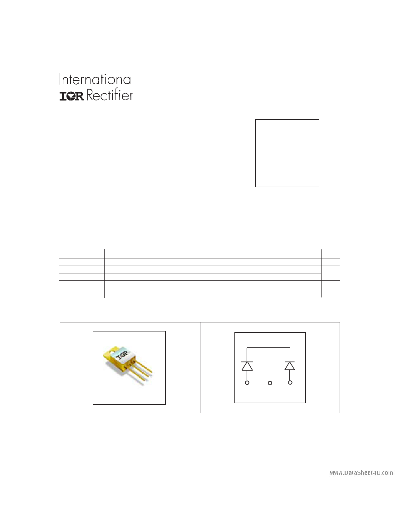
| Descripción | Soft Recovery Diode | |
| Fabricantes | International Rectifier | |
| Logotipo | ||
Hay una vista previa y un enlace de descarga de HFA35HB60C (archivo pdf) en la parte inferior de esta página. Total 5 Páginas | ||
|
No Preview Available !
www.DataSheet4U.com
PD - 20378B
FRED
HFA35HB60C
Ultrafast, Soft Recovery Diode
Features
• Reduced RFI and EMI
• Reduced Snubbing
• Extensive Characterization of Recovery Parameters
• Hermetic
• Electrically Isolated
• Ceramic Eyelets
VR = 600V
VF = 1.9V
Qrr = 270nC
di(rec)M /dt = 345A/µs
Description
These Ultrafast, soft recovery diodes are optimized to reduce losses and EMI/RFI in high frequency power
conditioning systems. An extensive characterization of the recovery behavior for different values of current,
temperature and di/dt simplifies the calculations of losses in the operating conditions. The softness of the recovery
eliminates the need for a snubber in most applications. These devices are ideally suited for power converters, motors
drives and other applications where switching losses are significant portion of the total losses.
Absolute Maximum Ratings
VR
IF(AV)
IFSM
PD @ TC = 25°C
TJ, TSTG
Parameter
Cathode to Anode Voltage (Per Leg)
Continuous Forward Current, TC =100 °C
Single Pulse Forward Current, TC = 25°C (Per Leg)
Maximum Power Dissipation
Operating Junction and Storage Temperature Range
Note: D.C. = 50% rect. wave
1/2 sine wave, 60 Hz , P.W. = 8.33 ms
Max.
600
30
150
63
-55 to +150
Units
V
A
W
°C
CASE STYLE
(ISOLATED BASE)
TO-254AA
ANODE COMMON ANODE
CATHODE
www.irf.com
DataSheet4 U .com
1
5/4/04
1 page 
www.DataSheet4U.com
HFA35HB60C
REVERSE RECOVERY CIRCUIT
IF
0
3
trr
ta
tb
VR = 200V
L = 70µH
0.01 Ω
D.U.T.
dif/dt
ADJUST G
D
IRFP250
S
Fig. 9 - Reverse Recovery Parameter Test Circuit
2 I RRM
Q rr 4
0.5 I RRM
di(rec)M/dt
5
0.75 IRRM
1 dif /dt
1. dif/dt - Rate of change of current
through zero crossing
2. IRRM - Peak reverse recovery current
3. trr - Reverse recovery time measured
from zero crossing point of negative
going IF to point where a line passing
through 0.75 IRRM and 0.50 IRRM
extrapolated to zero current
4. Qrr - Area under curve defined by trr
and IRRM
trr X IRRM
Qrr =
2
5. di(rec)M/dt - Peak rate of change of
current during tb portion of trr
Fig. 10 - Reverse Recovery Waveform and Definitions
Case Outline and Dimensions — TO-254AA
3.78 [.149]
3.53 [.139]
A
13.84 [.545]
13.59 [.535]
6.60 [.260]
6.32 [.249]
0.12 [.005]
1.27 [.050]
1.02 [.040]
17.40 [.685]
16.89 [.665]
123
20.32 [.800]
20.07 [.790]
13.84 [.545]
13.59 [.535]
C 17.40 [.685]
16.89 [.665]
3.81 [.150]
2X
3X
1.14 [.045]
0.89 [.035]
0.36 [.014] B A
NOT ES :
1. DIMENS IONING & TOLERANCING PER AS ME Y14.5M-1994.
2. ALL DIME NS IONS ARE S HOWN IN MILLIMETERS [INCHES ].
3. CONTROLLING DIMENS ION: INCH.
4. CONFORMS TO JE DE C OUT LINE TO-254AA.
PIN ASSIGNMENTS
1 = ANODE 1
2 = COMMON CATHODE
3 = ANODE 2
B
0.84 [.033]
MAX.
3.81 [.150]
www.irf.com
WORLD HEADQUARTERS: 233 Kansas St., El Segundo, California 90245, Tel: (310) 252-7105
IR LEOMINSTER: 205 Crawford St., Leominster, Massachusetts 01453, Tel: (978) 534-5776
Data and specifications subject to change without notice.
05/2004
5
DataSheet4 U .com
5 Page | ||
| Páginas | Total 5 Páginas | |
| PDF Descargar | [ Datasheet HFA35HB60C.PDF ] | |
Hoja de datos destacado
| Número de pieza | Descripción | Fabricantes |
| HFA35HB60 | Soft Recovery Diode | International Rectifier |
| HFA35HB60C | Soft Recovery Diode | International Rectifier |
| Número de pieza | Descripción | Fabricantes |
| SLA6805M | High Voltage 3 phase Motor Driver IC. |
Sanken |
| SDC1742 | 12- and 14-Bit Hybrid Synchro / Resolver-to-Digital Converters. |
Analog Devices |
|
DataSheet.es es una pagina web que funciona como un repositorio de manuales o hoja de datos de muchos de los productos más populares, |
| DataSheet.es | 2020 | Privacy Policy | Contacto | Buscar |