|
|
|
PDF SC1404 Data sheet ( Hoja de datos )
| Número de pieza | SC1404 | |
| Descripción | Mobile Multi-Output PWM Controller | |
| Fabricantes | Semtech Corporation | |
| Logotipo | ||
Hay una vista previa y un enlace de descarga de SC1404 (archivo pdf) en la parte inferior de esta página. Total 27 Páginas | ||
|
No Preview Available !
www.DataSheet4U.com
SC1404
Mobile Multi-Output PWM Controller
with Virtual Current SenseTM
POWER MANAGEMENT
Description
Features
The SC1404 is a multiple-output power supply controller designed
to power battery operated systems. The SC1404 provides syn-
chronous rectified buck converter control for two power supplies.
An efficiency of 95% can be achieved. The SC1404 uses
Semtech’s proprietary Virtual Current SenseTM technology along
with external error amplifier compensation to achieve enhanced
stability and DC accuracy over a wide range of output filter compo-
nents while maintaining fixed frequency operation. The SC1404
also provides two linear regulators for system housekeeping. The
5V linear regulator takes its input from the battery; for efficiency,
the output is switched to the 5V output when available. The 12V
linear regulator output is generated from a coupled inductor off
the 5V switching regulator.
Control functions include: power up sequencing, soft start, power-
good signaling, and frequency synchronization. Line and load
regulation is to +/-1% of the output voltage. The internal oscilla-
tor can be adjusted to 200 kHz or 300 kHz or synchronized to an
external clock. The MOSFET drivers provide >1A peak drive cur-
rent for fast MOSFET switching.
The SC1404 includes a PSAVE# input to select pulse skipping
mode for high efficiency at light load, or fixed frequency mode for
low noise operation.
6 to 30V input range (operation possible below 6V)
3.3V and 5V dual synchronous outputs
Fixed-frequency or PSAVE for maximum efficiency over
wide load current range
5V/50mA linear regulator
12V/200mA linear regulator
Virtual Current Sense TM for enhanced stability
Accurate low-loss current limiting
Out-of-phase switching reduces input capacitance
External compensation supports wide range of
output filter components for reduced cost
Programmable power-up sequence
Power Good output
Output overvoltage & overcurrent protection with output
undervoltage shutdown
4µA typical shutdown current
6mW typical quiescent power
Applications
Notebook and Subnotebook Computers
Automotive Electronics
Desktop DC-DC Converters
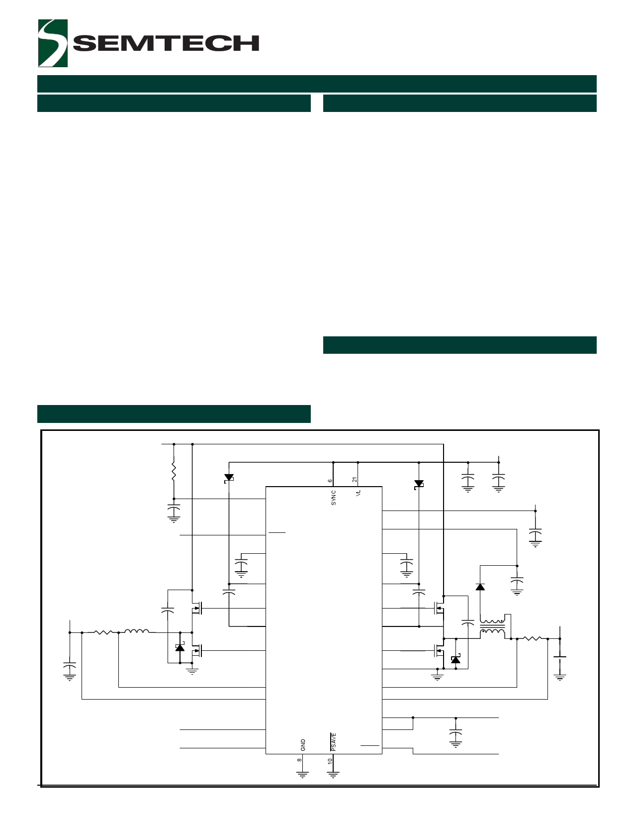
Typical Application Circuit
IN P U T + 6V to + 30V
S C 1404 O N /O F F
10
0.22uF
S C 1404 O N /O F F
+3V O U TP U T
+
0.1uF
L1
3V O N /O F F
5V O N /O F F
0.1uF
U4
22 V+
23 SHDN
3 COMP3
C7
25 BST3
27 DH3
26 PHASE3
24 DL3
SC1404
1 CSH3
2 CSL3
28 RUN/ON3
7 ON5
12OUT 4
VDD 5
COMP5 12
C11
BST5 18
0.1uF
DH5 16
PHASE5 17
DL5 19
PGND 20
CSH5
CSL5
14
13
SEQ
REF
15
9
RESET 11
+5V A LW A Y S O N
0.1uF
+
4.7uF
+12V O U TP U T
+ 4.7uF
0.1uF
+
2.2uF
T1
+5V O U TP U T
+
+
0.1uF
+ 2.5V R E F
POW ER GOOD
Revision 4, July 2003
1
www.semtech.com
1 page 
SC1404
POWER MANAGEMENT
Electrical Characteristics Cont.
Unless otherwise noted: V+ = 15V, both PWMs on, SYNC = 0V, VL load = 0mA, REF load = 0mA, PSAVE# = 0V, TA =-40 to 85°C.
Typical values are at TA = +25°C. Circuit = Typical Application Circuit
PARAMETER
CODE
CONDITIONS
MIN TYP
MAX
UNITS
Input Leakage Current
PSAVE#, ON5, SYNC
ILP, IL5, ILSN
SEQ = REF
-1 +1 µA
Input Leakage Current - ON3 IL3
ON3 = 15V
-2 +2 µA
Input Leakage Current
SHDN#
ILSD
SHDN# = 15V
-1 3 +10 µA
Logic Output Low Voltage
VORSTL
RESET#, ISINK = 4mA
0.4 V
Logic Output High Current IORSTH
RESET# = 3.5V
1 mA
ON5 Pull-down Resistance RON5
ON5, ON3 = 0V, (SEQ = REF)
100 Ω
Gate Driver Sink/Source
IDL3, IDH3,
DL3, DH3, DL5, DH5, forced to 2.5V
1
A
Current
IDL5, IDH5
Gate Driver On-Resistance
RGBH3, RGHP3,
RGBH5, RGHP5,
RGVL3, RGLG3
RGVL5, RGLG5
BST3 to DH3, DH3 to PHASE3,
BST5 to DH5, DH5 to PHASE5,
VL to DL3, DL3 to PGND,
VL to DL5, DL5 to PGND
1.5 7
Ω
Non-Overlap Threshold
ZNOV T
PHASE3, PHASE5 to GND
1.0 V
Shoot-through (Non-Overlap)
Delay
DHx falling edge to DLx rising edge
DLx falling edge to DHx rising edge
(1V threshold on DHx and DLx, no
external capacitance on DL or DH)
10 17 25 nsec
35 75 115 nsec
12V LINEAR REGULATOR
VDD Shunt Threshold
VDDSHN
Rising edge, hysteresis = 5%
17
21 V
VDD Shunt Current
IVDDST
VDD = 20V
5 10 30 mA
VDD Leakage Current
IVDDLK
VDD = 5V, Standby mode
30 µA
12OUT Output Voltage
VOUT12
0mA < Load < 200mA
11.55 12.1 12.75 V
12OUT Current Limit
ILIM12
12OUT forced to 11V, VDD = 13V
200
mA
12OUT Regulation Threshold V12THR
Falling edge
11.9 V
Quiescent VDD Current
I12Q
VDD = 18V, run mode, no 12OUT load
Notes:
(1) This device is ESD sensitive. Use of standard ESD handling procedures required.
(2) Applicable from 0 to +85°C.
80 100 µA
2003 Semtech Corp.
5
www.semtech.com
5 Page 
SC1404
POWER MANAGEMENT
Functional Information
SC1404 Startup Sequence Chart
SEQ
REF
REF
REF
REF
GND
GND
VL
VL
ON3
LOW
LOW
HIGH
HIGH
LOW
HIGH
LOW
HIGH
ON5 RESET#
DESCRIPTION
LOW Follows 3.3V SMPS.
Independant start control mode. Both SMPSs off.
HIGH
Low.
5V SMPS ON, 3.3V SMPS OFF.
LOW Follows 3.3V SMPS.
3.3V SMPS ON, 5V SMPS OFF.
HIGH
Follows 3.3V SMPS.
Both SMPSs on.
X Low.
Both SMPSs off.
HIGH/LOW High after both outputs are in 5V starts when ON3 goes high. If ON5= HIGH, 3V is
regulation.
on. IF ON5 = LOW, 3V is off.
X Low.
Both SMPSs off.
HIGH/LOW High after both outputs are in 3V starts when ON3 goes high. If ON5 = HIGH, 5V is
regulation.
on. IF ON5 = LOW, 5V is off.
Applications Information
Reference Circuit Design
Introduction
The SC1404 is a versatile dual switching regulator with fixed 5V
and 3.3V outputs . In addition, there is an on-chip 5V linear regulator
capable of supplying 50mA output current and a 12V linear regulator
able to provide 200mA. The SC1404 is designed for notebook
applications but has is suited to applications where high efficiency,
small package, and low cost are required.
Design Guidelines
maximum load. However, in order to speed up the output transient
response, ripple current can be much higher. In this design, we are
going to set the ripple current to be 40% of maximum load. So
once the ripple voltage specification is determined, the capacitor
ESR is chosen. The output ripple voltage is usually specified at +/
- 1% of the output voltage.
For the reference circuit 3.3V switcher, we selected a maximum
ripple voltage of 33mV. Choosing one 180uF, 4V Panasonic SP
Polymer Aluminum Electrolytic Cap, of which ESR is 15 mΩ , sets
the maximum ripple current as follows:
∆IO
=
∆VO _ MAX
ESR
∆IO
=
0.033V
0.015Ω
=
2.2A
The schematic for the reference circuit is shown on page 22. The
reference circuit is configured as follows:
Switching Regulator 1
Switching Regulator 2
Linear Regulator 1
Linear Regulator 2
Vout1 = 3.3V @ 6A
Vout2 = 5.0V @ 6A
Vout3 = 12V, 200mA
Vout3 = 5.0V @ 50mA
Checking to see if the maximum RMS current can be met by the
SP cap.
IRMS =
I12 + I1 ⋅I2 + I22
3
I1
=
−
∆IO
2
I2
=
+
∆IO
2
Designing the Output Filter
Before calculating the output filter inductance and output
capacitance, an acceptable amount of output ripple current must
be determined. The maximum allowable ripple current depends
on the transient requirement of the power supply. Under normal
situation, the ripple current is usually set around 10 to 20% of the
Irms=0.635 A << Irms_rated=3.0A
The output inductance can now be found by:
LO
=
(VIN _ NOM − VO) ⋅DNOM ⋅ TS
∆IO
2003 Semtech Corp.
11
www.semtech.com
11 Page | ||
| Páginas | Total 27 Páginas | |
| PDF Descargar | [ Datasheet SC1404.PDF ] | |
Hoja de datos destacado
| Número de pieza | Descripción | Fabricantes |
| SC140 | (SCxxx) Triacs | Digitron Electronic |
| SC1401 | HIGH PERFORMANCE SYNCHRONOUS BUCK CONTROLLER WITH LDO FOR PORTABLE POWER | Semtech Corporation |
| SC1401ISS | HIGH PERFORMANCE SYNCHRONOUS BUCK CONTROLLER WITH LDO FOR PORTABLE POWER | Semtech Corporation |
| SC1402 | Multi-Output/ Low-Noise Power Supply Controller for Notebook Computers | Semtech Corporation |
| Número de pieza | Descripción | Fabricantes |
| SLA6805M | High Voltage 3 phase Motor Driver IC. |
Sanken |
| SDC1742 | 12- and 14-Bit Hybrid Synchro / Resolver-to-Digital Converters. |
Analog Devices |
|
DataSheet.es es una pagina web que funciona como un repositorio de manuales o hoja de datos de muchos de los productos más populares, |
| DataSheet.es | 2020 | Privacy Policy | Contacto | Buscar |