|
|
|
PDF CAT1321 Data sheet ( Hoja de datos )
| Número de pieza | CAT1321 | |
| Descripción | (CAT1320 / CAT1321) Supervisory Circuits | |
| Fabricantes | Catalyst Semiconductor | |
| Logotipo | ||
Hay una vista previa y un enlace de descarga de CAT1321 (archivo pdf) en la parte inferior de esta página. Total 18 Páginas | ||
|
No Preview Available !
www.DataSheet4U.com
CAT1320, CAT1321
Supervisory Circuits with I2C Serial 32K CMOS EEPROM
ALOGEN FR
LEA D F REETM
FEATURES
I Precision power supply voltage monitor
— 5V, 3.3V and 3V systems
- +5.0V (+/- 5%, +/- 10%)
- +3.3V (+/- 5%, +/- 10%)
- +3.0V (+/- 10%)
I Active low reset, CAT1320
I Active high reset, CAT1321
I Valid reset guaranteed at VCC=1V
I 400kHz I2C bus
I 3.0V to 5.5V operation
I Low power CMOS technology
I 64-Byte page write buffer
I 1,000,000 Program/Erase cycles
I 100 year data retention
I 8-pin DIP, SOIC, TSSOP and TDFN packages
I Industrial temperature range
DESCRIPTION
The CAT1320 and CAT1321 are complete memory and
supervisory solutions for microcontroller-based systems.
A 32kbit serial EEPROM memory and a system power
supervisor with brown-out protection are integrated
together in low power CMOS technology. Memory
interface is via a 400kHz I2C bus.
The CAT1320 provides a precision VCC sense circuit
and drives an open drain output, RESET low whenever
VCC falls below the reset threshold voltage.
The CAT1321 provides a precision VCC sense circuit
that drives an open drain output, RESET high whenever
VCC falls below the reset threshold voltage.
The power supply monitor and reset circuit protect
memory and system controllers during power up/down
and against brownout conditions. Five reset threshold
voltages support 5V, 3.3V and 3V systems. If power
supply voltages are out of tolerance reset signals become
active, preventing the system microcontroller, ASIC or
peripherals from operating. Reset signals become inactive
typically 200 ms after the supply voltage exceeds the reset
threshold level. With both active high and low reset options,
interface to microcontrollers and other ICs is simple. In
addition, the RESET (CAT1320) pin can be used as an
input for push-button manual reset capability.
The CAT1320/21 memory features a 64-byte page. In
addition, hardware data protection is provided by a VCC
sense circuit that prevents writes to memory whenever VCC
falls below the reset threshold or until VCC reaches the reset
threshold during power up.
Available packages include an 8-pin DIP, SOIC, TSSOP
and 4.9 x 3mm TDFN.
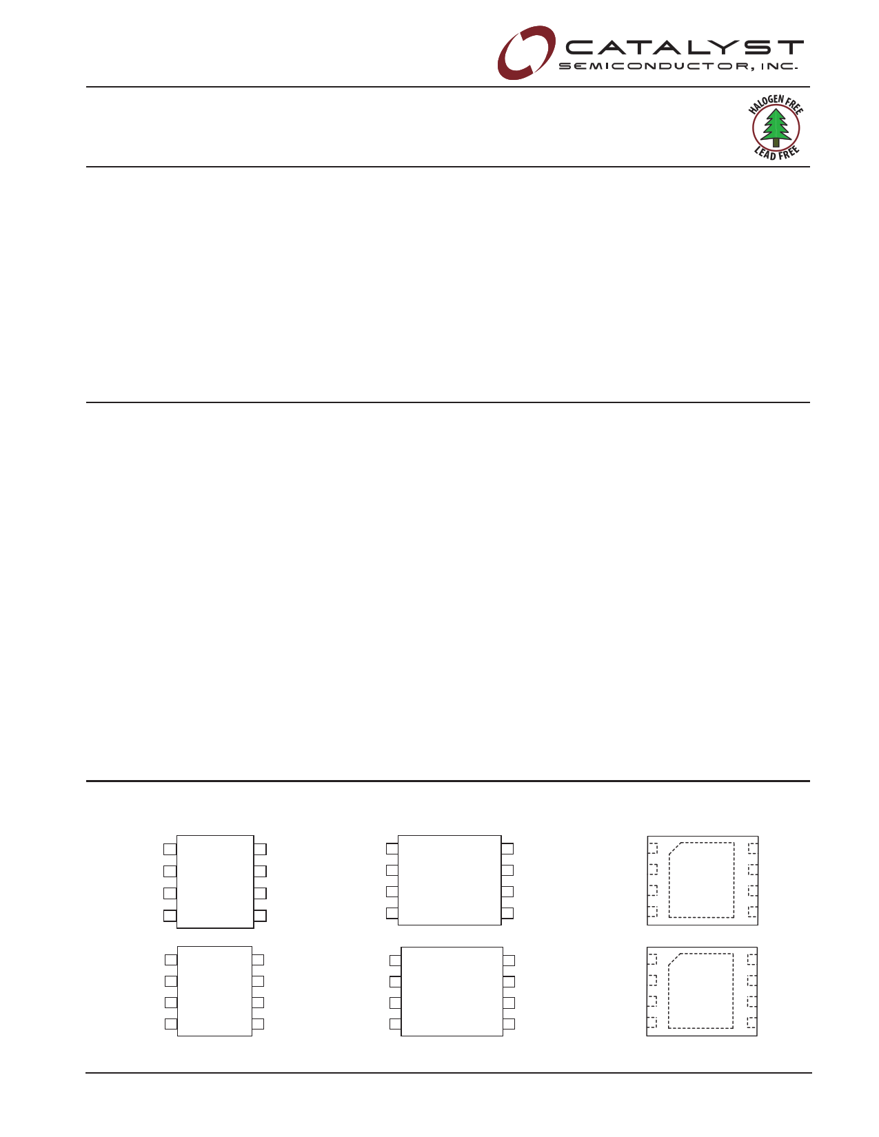
PIN CONFIGURATION
PDIP (P, L) SOIC (J, W)
A0 1
A1 2
A2 3
VSS 4
CAT1320
8 VCC
7 RESET
6 SCL
5 SDA
TSSOP (U, Y)
A0 1
A1 2
A2 3
VSS 4
CAT1320
8 VCC
7 RESET
6 SCL
5 SDA
TDFN PACKAGE: 4.9MM X 3MM
(RD2, ZD2)
A0 1
A1 2
A2 3
VSS 4
CAT1320
8 VCC
7 RESET
6 SCL
5 SDA
A0 1
A1 2
A2 3
VSS 4
CAT1321
8 VCC
7 RESET
6 SCL
5 SDA
A0 1
A1 2
A2 3
VSS 4
CAT1321
8 VCC
7 RESET
6 SCL
5 SDA
A0 1
A1 2
A2 3
VSS 4
CAT1321
8 VCC
7 RESET
6 SCL
5 SDA
© 2005 by Catalyst Semiconductor, Inc.
Characteristics subject to change without notice
1
Doc. No. 20585, Rev. 00
1 page 
Advance Information
CAT1320, CAT1321
RESET CIRCUIT A.C. CHARACTERISTICS
Symbol
Parameter
Test
Conditions
Min
Typ Max
tPURST
tRPD
tGLITCH
MR Glitch
Reset Timeout
VTH to RESET output Delay
VCC Glitch Reject Pulse Width
Manual Reset Glitch Immunity
Note 2
Note 3
Note 4, 5
Note 5
130 200 270
5
30
100
tMRW
MR Pulse Width
Note 5
5
Units
ms
µs
ns
ns
µs
POWER-UP TIMING5,6
Symbol
Parameter
Test
Conditions
Min
Typ Max
Units
tPUR Power-Up to Read Operation
tPUW Power-Up to Write Operation
270 ms
270 ms
Notes:
1. Test Conditions according to “AC Test Conditions” table.
2. Power-up, Input Reference Voltage VCC = VTH, Reset Output Reference Voltage and Load according to “AC Test Conditions” Table
3. Power-Down, Input Reference Voltage VCC = VTH, Reset Output Reference Voltage and Load according to “AC Test Conditions” Table
4. VCC Glitch Reference Voltage = VTHmin; Based on characterization data
5. This parameter is characterized initially and after a design or process change that affects the parameter. Not 100% tested.
6. tPUR and tPUW are the delays required from the time VCC is stable until the specified memory operation can be initiated.
AC TEST CONDITIONS
Input pulse voltages
Input rise and fall times
Input reference voltages
Output reference voltages
Output Load
0.2VCC to 0.8VCC
10 ns
0.3VCC, 0.7VCC
0.5VCC
Current Source: IOL = 3mA;
CL = 100pF
RELIABILITY CHARACTERISTICS
Symbol
NEND(1)
TDR(1)
VZAP(1)
ILTH(1)(2)
Parameter
Endurance
Data Retention
ESD Susceptibility
Latch-Up
Reference Test Method
Min
MIL-STD-883, Test Method 1033 1,000,000
MIL-STD-883, Test Method 1008 100
MIL-STD-883, Test Method 3015 2000
JEDEC Standard 17
100
Max
Notes:
1. This parameter is tested initially and after a design or process change that affects the parameter. Not 100% tested.
2. Latch-up protection is provided for stresses up to 100mA on input and output pins from -1V to VCC + 1V.
Units
Cycles/Byte
Years
Volts
mA
5 Doc No. 25085, Rev. 00
5 Page 
Advance Information
CAT1320, CAT1321
Acknowledge Polling
Disabling of the inputs can be used to take advantage of
the typical write cycle time. Once the stop condition is
issued to indicate the end of the host’s write opration, the
CAT1320/21 initiates the internal write cycle. ACK polling
can be initiated immediately. This involves issuing the
start condition followed by the slave address for a write
operation. If the device is still busy with the write operation,
no ACK will be returned. If a write operation has
completed, an ACK will be returned and the host can
then proceed with the next read or write operation.
Read Operations
The READ operation for the CAT1320/21 is initiated in
the same manner as the write operation with one
exception, that R/W bit is set to one. Three different
READ operations are possible: Immediate/Current
Address READ, Selective/Random READ and
Sequential READ.
Figure 10. Immediate Address Read Timing
SCL
SDA
BUS ACTIVITY:
MASTER
S
T
A
R
T
SDA LINE S
SLAVE
ADDRESS
A
C
K
DATA
S
T
O
P
P
N
O
A
C
K
89
8TH BIT
DATA OUT
NO ACK
STOP
11 Doc No. 25085, Rev. 00
11 Page | ||
| Páginas | Total 18 Páginas | |
| PDF Descargar | [ Datasheet CAT1321.PDF ] | |
Hoja de datos destacado
| Número de pieza | Descripción | Fabricantes |
| CAT1320 | (CAT1320 / CAT1321) Supervisory Circuits | Catalyst Semiconductor |
| CAT1321 | (CAT1320 / CAT1321) Supervisory Circuits | Catalyst Semiconductor |
| Número de pieza | Descripción | Fabricantes |
| SLA6805M | High Voltage 3 phase Motor Driver IC. |
Sanken |
| SDC1742 | 12- and 14-Bit Hybrid Synchro / Resolver-to-Digital Converters. |
Analog Devices |
|
DataSheet.es es una pagina web que funciona como un repositorio de manuales o hoja de datos de muchos de los productos más populares, |
| DataSheet.es | 2020 | Privacy Policy | Contacto | Buscar |