|
|
|
PDF WM8782 Data sheet ( Hoja de datos )
| Número de pieza | WM8782 | |
| Descripción | Stereo ADC | |
| Fabricantes | Wolfson Microelectronics | |
| Logotipo | ||
Hay una vista previa y un enlace de descarga de WM8782 (archivo pdf) en la parte inferior de esta página. Total 20 Páginas | ||
|
No Preview Available !
w
24-Bit, 192kHz Stereo ADC
WM8782
DESCRIPTION
The WM8782 is a high performance, low cost stereo audio
ADC designed for recordable media applications.
The device offers stereo line level inputs along with two
control input pins (FORMAT, IWL) to allow operation of the
audio interface in three industry standard modes. An
internal op-amp is integrated on the front end of the chip to
accommodate analogue input signals greater than 1Vrms.
The device also has a high pass filter to remove residual
DC offsets.
WM8782 offers Master or Slave mode clocking schemes.
A control input pin M/S is used to allow Slave mode
operation or Master mode operation. A stereo 24-bit multi-
bit sigma-delta ADC is used with 128x, 64x or 32x over-
sampling, according to sample rate. Digital audio output
word lengths from 16-24 bits and sampling rates from 8kHz
to 192kHz are supported.
The device is a hardware controlled device and is supplied
in a 20-lead SSOP package.
The device is available over a functional temperature range of
-40C to +85C
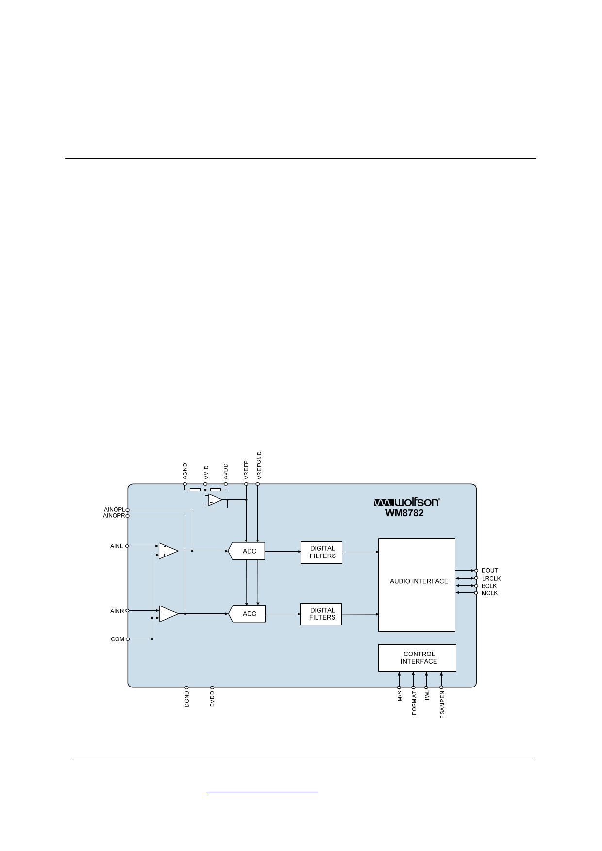
BLOCK DIAGRAM
FEATURES
SNR 100dB (‘A’ weighted @ 48kHz)
THD -93dB (at –1dB)
Sampling Frequency: 8 – 192kHz
Master or Slave Clocking Mode
System Clock (MCLK): 128fs, 192fs, 256fs, 384fs, 512fs,
768fs
- Audio Data Interface Modes
16-24 bit I2S, 16-24 bit Left, 16-24 bit Right Justified
Supply Voltages
- Analogue: 2.7 to 5.5V
- Digital core: 2.7V to 3.6V
20-lead SSOP or 20-lead TSSOP package
Accelerated Lifetime Screened Devices available.
APPLICATIONS
Recordable DVD Players
Personal Video Recorders
STB
Studio Audio Processing Equipment
Automotive
WOLFSON MICROELECTRONICS plc
To receive regular email updates, sign up at http://www.wolfsonmicro.com/enews
Production Data, April 2010, Rev 4.7
Copyright 2010 Wolfson Microelectronics plc
1 page 
Production Data
WM8782
ABSOLUTE MAXIMUM RATINGS
Absolute Maximum Ratings are stress ratings only. Permanent damage to the device may be caused by continuously
operating at or beyond these limits. Device functional operating limits and guaranteed performance specifications are given
under Electrical Characteristics at the test conditions specified.
ESD Sensitive Device. This device is manufactured on a CMOS process. It is therefore generically susceptible
to damage from excessive static voltages. Proper ESD precautions must be taken during handling and storage
of this device.
Wolfson tests its package types according to IPC/JEDEC J-STD-020B for Moisture Sensitivity to determine acceptable storage
conditions prior to surface mount assembly. These levels are:
MSL1 = unlimited floor life at <30C / 85% Relative Humidity. Not normally stored in moisture barrier bag.
MSL2 = out of bag storage for 1 year at <30C / 60% Relative Humidity. Supplied in moisture barrier bag.
MSL3 = out of bag storage for 168 hours at <30C / 60% Relative Humidity. Supplied in moisture barrier bag.
The Moisture Sensitivity Level is specified in Ordering Information.
CONDITION
Digital supply voltage
Analogue supply voltage
Voltage range digital inputs
Voltage range analogue inputs
Ambient temperature (supplies applied)
Storage temperature
Pb free package body temperature (reflow 10 seconds)
Package body temperature (soldering 2 minutes)
Notes:
1. Analogue and digital grounds must always be within 0.3V of each other.
MIN
-0.3V
-0.3V
DGND -0.3V
AGND -0.3V
-55C
-65C
MAX
+4.5V
+7V
DVDD + 0.3V
AVDD +0.3V
+125C
+150C
+260C
+183C
THERMAL PERFORMANCE
PARAMETER
Thermal resistance – junction to
ambient
SYMBOL
RθJA
TEST CONDITIONS
MIN TYP
81
See note 1
MAX
UNIT
°C/W
Notes:
1. Figure given for package mounted on 4-layer FR4 according to JESD51-7. (No forced air flow is assumed).
2. Thermal performance figures are estimated.
w
PD, April 2010, Rev 4.7
5
5 Page 
Production Data
WM8782
DEVICE DESCRIPTION
INTRODUCTION
ADC
The WM8782 is a stereo 24-bit ADC designed for demanding recording applications such as DVD
recorders, studio mixers, PVRs, and AV amplifiers. The WM8782 consists of stereo line level inputs,
followed by a sigma-delta modulator and digital filtering.
The device offers stereo line level inputs along with two control input pins (FORMAT, IWL) to allow
operation of the audio interface in three industry standard modes (left justified, right justified or I2S) .
An internal op-amp is integrated on the front end of the chip to accommodate analogue input signals
greater than 1Vrms. The device also has a high pass filter to remove residual DC offsets.
The WM8782 offers Master or Slave mode clocking schemes. A control input pin M/S is used to allow
Slave mode or Master mode operation. The WM8782 supports master clock rates from 128fs to 768fs
and digital audio output word lengths from 16-24 bits. Sampling rates from 8kHz to 192kHz are
supported, delivering high SNR operating with 128x, 64x or 32x over-sampling, according to the
sample rate.
The line inputs are biased internally through the operational amplifier to VMID.
The WM8782 uses a multi-bit over sampled sigma-delta ADC. A single channel of the ADC is
illustrated in Figure 5.
LIN/RIN
ANALOG
INTEGRATOR
MULTI
BITS
TO ADC DIGITAL FILTERS
Figure 5 Multi-Bit Oversampling Sigma Delta ADC Schematic
The use of multi-bit feedback and high oversampling rates reduces the effects of jitter and high
frequency noise.
The ADC Full Scale input is 1.0V rms at AVDD = 5.0 volts. Any input voltage greater than full scale
will possibly overload the ADC and cause distortion. Note that the full scale input has a linear
relationship with AVDD. The internal op-amp and appropriate resistors can be used to reduce signals
greater than 1Vrms before they reach the ADC.
The ADC filters perform true 24 bit signal processing to convert the raw multi-bit oversampled data
from the ADC to the correct sampling frequency to be output on the digital audio interface.
ADC OUTPUT PHASE
In the input to output data-path, the digital output data DOUT, is a phase inverted representation of
the analogue input signal.
ADC DIGITAL FILTER
The ADC digital filters contain a digital high pass filter. The high-pass filter response detailed in Digital
Filter Characteristics. The operation of the high pass filter removes residual DC offsets that are
present on the audio signal.
.
w
PD, April 2010, Rev 4.7
11
11 Page | ||
| Páginas | Total 20 Páginas | |
| PDF Descargar | [ Datasheet WM8782.PDF ] | |
Hoja de datos destacado
| Número de pieza | Descripción | Fabricantes |
| WM8781 | Stereo ADC | Wolfson Microelectronics |
| WM8782 | Stereo ADC | Wolfson Microelectronics |
| WM8782A | Stereo ADC | Wolfson Microelectronics |
| WM8785 | Stereo ADC | Wolfson Microelectronics |
| Número de pieza | Descripción | Fabricantes |
| SLA6805M | High Voltage 3 phase Motor Driver IC. |
Sanken |
| SDC1742 | 12- and 14-Bit Hybrid Synchro / Resolver-to-Digital Converters. |
Analog Devices |
|
DataSheet.es es una pagina web que funciona como un repositorio de manuales o hoja de datos de muchos de los productos más populares, |
| DataSheet.es | 2020 | Privacy Policy | Contacto | Buscar |