|
|
|
PDF HI5703 Data sheet ( Hoja de datos )
| Número de pieza | HI5703 | |
| Descripción | 40 MSPS A/D Converter | |
| Fabricantes | Intersil Corporation | |
| Logotipo | ||
Hay una vista previa y un enlace de descarga de HI5703 (archivo pdf) en la parte inferior de esta página. Total 18 Páginas | ||
|
No Preview Available !
TM
FOR
NETWHDEEaHtSIa5IG7SN6h7Se/,4eICtNBTEORRSHILI5R7E46CKOCMBMENDNSovember
1998
HI5703
File Number 3950.7
10-Bit, 40 MSPS A/D Converter
The HI5703 is a monolithic, 10-bit, analog-to-digital
[ /Title converter fabricated in Intersil’s BiCMOS process. It is
(HI5703 designed for high speed applications where wide bandwidth
) and low power consumption are essential. Its 40 MSPS
/Sub-
speed is made possible by a fully differential pipeline
ject (10- architecture with an internal sample and hold.
Bit, 40
MSPS
A/D
Con-
verter)
/Author
()
The HI5703 has excellent dynamic performance while
consuming only 400mW power at 40 MSPS. Data output
latches are provided which present valid data to the output
bus with a latency of 7 clock cycles. It is pin-to-pin
compatible with the HI5702.
For lower power consumption or internal reference, please
refer to the HI5746 or HI5767.
/Key-
words Ordering Information
(Intersil
Semi-
TEMP.
PART NUMBER RANGE (oC)
PACKAGE
PKG.
NO.
conduc- HI5703KCB
0 to 70 28 Ld SOIC (W)
M28.3
tor, HI5703EVAL
25 Evaluation Board
A/D,www.DataSheet4U.com
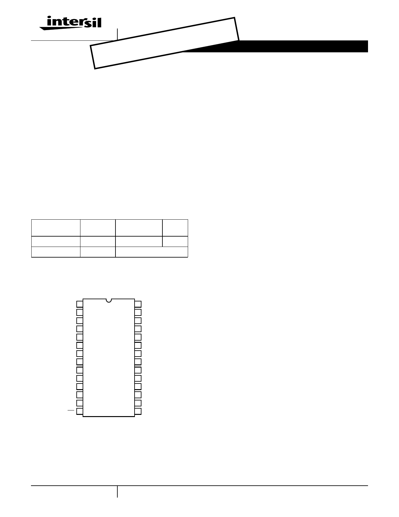
Analog Pinout
to Digi-
tal Con-
HI5703
(SOIC)
TOP VIEW
verter,
Narrow
DVCC1 1
28 D0
Band,
DGND 2
27 D1
Com-
munica-
tions,
High
Speed
Convert-
ers,
High
DVCC1 3
DGND 4
AVCC 5
AGND 6
VREF+ 7
VREF- 8
VIN+ 9
VIN- 10
VDC 11
26 D2
25 D3
24 D4
23 DVCC2
22 CLK
21 DGND
20 D5
19 D6
18 D7
Resolu-
AGND 12
17 D8
tion
Convert-
AVCC 13
OE 14
16 D9
15 DFS
ers, Bas-
estation,
Features
• Sampling Rate . . . . . . . . . . . . . . . . . . . . . . . . . . 40 MSPS
• 8.55 Bits Guaranteed at fIN = 10MHz
• Low Power
• Wide Full Power Input Bandwidth. . . . . . . . . . . . . 250MHz
• On Chip Sample and Hold
• Fully Differential or Single-Ended Analog Input
• Single Supply Voltage. . . . . . . . . . . . . . . . . . . . . . . . . +5V
• TTL Compatible Interface
• 3.3V Digital Outputs Available
Applications
• Professional Video Digitizing
• Medical Imaging
• Digital Communication Systems
• High Speed Data Acquisition
• Additional Reference Documents
- AN9534 Using the HI5703 Evaluation Board
- AN9413 Driving the Analog Input of the HI5702
- AN9214 Using Intersil High Speed A/D Converters
4-1 CAUTION: These devices are sensitive to electrostatic discharge; follow proper IC Handling Procedures.
1-888-7143 | Copyright © Intersil Corporation 1998
1 page 
Electrical Specifications
CAVycClCe;=CDLV=C2C01pF=;DTVAC=C225=oC+;5D.0iVff;eVreRnEtiFa+l A=n3a.lo2g5VIn; pVuRt;EUF n- l=es2s.0OVt;hfeSrw=is3e6
MSPS at
Specified
50% Duty
(Continued)
PARAMETER
TEST CONDITION
MIN
TYP
MAX
UNITS
Spurious Free Dynamic Range, SFDR
Intermodulation Distortion, IMD
Differential Gain Error
Differential Phase Error
Transient Response
fIN = 1MHz
fIN = 5MHz
fIN = 10MHz
f1 = 1MHz, f2 = 1.02MHz
fS = 17.72MHz, 6 Step, Mod Ramp
fS = 17.72MHz, 6 Step, Mod Ramp
-
-
54
-
-
-
-
66
64
63
-59
0.5
0.1
1
- dBc
- dBc
- dBc
- dBc
-%
- Degree
- Cycle
Over-Voltage Recovery
0.2V Overdrive
- 1 - Cycle
ANALOG INPUT
Maximum Peak-to-Peak Differential Analog In-
put Range (VIN+ - VIN-)
Maximum Peak-to-Peak Single-Ended
Analog Input Range
Analog Input Resistance, RIN
Analog Input Capacitance, CIN
Analog Input Bias Current, IB+ or IB-
Differential Analog Input Bias Current
IB DIFF = (IB+ - IB-)
Analog Input Common Mode Voltage Range
(VIN+ + VIN-) / 2
Full Power Input Bandwidth (FPBW)
(Note 3)
(Note 3)
Differential Mode (Note 1)
-
-
-
-
-10
-
0.625
-
±1.25
2.5
1
7
-
±0.5
-
250
-
-
-
-
+10
-
4.375
-
V
V
MΩ
pF
µA
µA
V
MHz
REFERENCE INPUT
Total Reference Resistance, RL
Reference Current
Positive Reference Voltage Input, VREF+
Negative Reference Voltage Input, VREF-
Reference Common Mode Voltage
(VREF+ + VREF-) / 2
DC BIAS VOLTAGE
DC Bias Voltage Output, VDC
Max Output Current
(Note 2)
(Note 2)
(Note 2)
300
2.5
-
1.95
2.575
400
3.125
3.25
2.0
2.625
500
4.2
3.3
-
2.675
Ω
mA
V
V
V
- 2.8 -
V
- - 1 mA
DIGITAL INPUTS
Input Logic High Voltage, VIH
Input Logic Low Voltage, VIL
Input Logic High Current, IIH
Input Logic Low Current, IIL
Input Capacitance, CIN
DIGITAL OUTPUTS
Output Logic Sink Current, IOL
Output Logic Source Current, IOH
Output Three-State Leakage Current, IOZ
Output Logic Sink Current, IOL
Output Logic Source Current, IOH
Output Three-State Leakage Current, IOZ
Output Capacitance, COUT
VIH = 5V
VIL = 0V
VO = 0.4V; DVCC2 = 5V
VO = 2.4V; DVCC2 = 5V
VO = 0/5V; DVCC2 = 5V
VO = 0.4V; DVCC2 = 3.3V
VO = 2.4V; DVCC2 = 3.3V
VO = 0/3.3V; DVCC2 = 3.3V
2.0 - - V
- - 0.8 V
- - 10.0 µA
- - 10.0 µA
- 7 - pF
1.6 -
- mA
-0.2 -
- mA
- ±1 ±10 µA
1.6 -
- mA
-0.2 -
- mA
- ±1 ±10 µA
- 5 - pF
4-5
5 Page 
Typical Performance Curves (Continued)
0dB
-10dB
-20dB
-30dB
-40dB
-50dB
-60dB
-70dB
-80dB
-90dB
-100dB
0
fIN = 1MHz
fS = 40 MSPS
200
400
600
800
1000
1200
1400
1600
1800
FREQUENCY BIN
FIGURE 14. 4096 POINT FFT SPECTRAL PLOT
2047
4-11
11 Page | ||
| Páginas | Total 18 Páginas | |
| PDF Descargar | [ Datasheet HI5703.PDF ] | |
Hoja de datos destacado
| Número de pieza | Descripción | Fabricantes |
| HI5702 | 40 MSPS A/D Converter | Intersil Corporation |
| HI5703 | 40 MSPS A/D Converter | Intersil Corporation |
| Número de pieza | Descripción | Fabricantes |
| SLA6805M | High Voltage 3 phase Motor Driver IC. |
Sanken |
| SDC1742 | 12- and 14-Bit Hybrid Synchro / Resolver-to-Digital Converters. |
Analog Devices |
|
DataSheet.es es una pagina web que funciona como un repositorio de manuales o hoja de datos de muchos de los productos más populares, |
| DataSheet.es | 2020 | Privacy Policy | Contacto | Buscar |