|
|
|
PDF HI5735 Data sheet ( Hoja de datos )
| Número de pieza | HI5735 | |
| Descripción | A/D Converter | |
| Fabricantes | Intersil Corporation | |
| Logotipo | ||
Hay una vista previa y un enlace de descarga de HI5735 (archivo pdf) en la parte inferior de esta página. Total 11 Páginas | ||
|
No Preview Available !
®
Data Sheet
July 2004
HI5735
FN4133.5
12-Bit, 80 MSPS, High Speed Video D/A
Converter
The HI5735 is a 12-bit, 80 MSPS, D/A converter which is
implemented in the Intersil BiCMOS 10V (HBC-10) process.
Operating from +5V and -5.2V, the converter provides
-20.48mA of full scale output current and includes an input
data register and bandgap voltage reference. Low glitch
energy and excellent frequency domain performance are
achieved using a segmented architecture. The digital inputs
are TTL/CMOS compatible and translated internally to ECL.
All internal logic is implemented in ECL to achieve high
switching speed with low noise. The addition of laser
trimming assures 12-bit linearity is maintained along the
entire transfer curve.
Ordering Information
TEMP.
PART NUMBER RANGE (°C)
PACKAGE
PKG.
DWG. #
HI5735KCB
0 to 70 28 Lead SOIC
M28.3
HI5735KCBZ (Note)
0 to 70
28 Lead SOIC
(Pb-free)
M28.3
www.DataSheet4U.com
NOTE: Intersil Pb-free products employ special Pb-free material
sets; molding compounds/die attach materials and 100% matte tin
plate termination finish, which is compatible with both SnPb and
Pb-free soldering operations. Intersil Pb-free products are MSL
classified at Pb-free peak reflow temperatures that meet or exceed
the Pb-free requirements of IPC/JEDEC J Std-020B.
Features
• Throughput Rate . . . . . . . . . . . . . . . . . . . . . . . . 80 MSPS
• Low Power . . . . . . . . . . . . . . . . . . . . . . . . . . . . . . .650mW
• Integral Linearity Error . . . . . . . . . . . . . . . . . . . . 0.75 LSB
• Low Glitch Energy . . . . . . . . . . . . . . . . . . . . . . . . . 3.0pV-s
• TTL/CMOS Compatible Inputs
• Improved Hold Time . . . . . . . . . . . . . . . . . . . . . . . . 0.25ns
• Excellent Spurious Free Dynamic Range
• Pb-free Available
Applications
• Professional Video
• Cable TV Headend Equipment
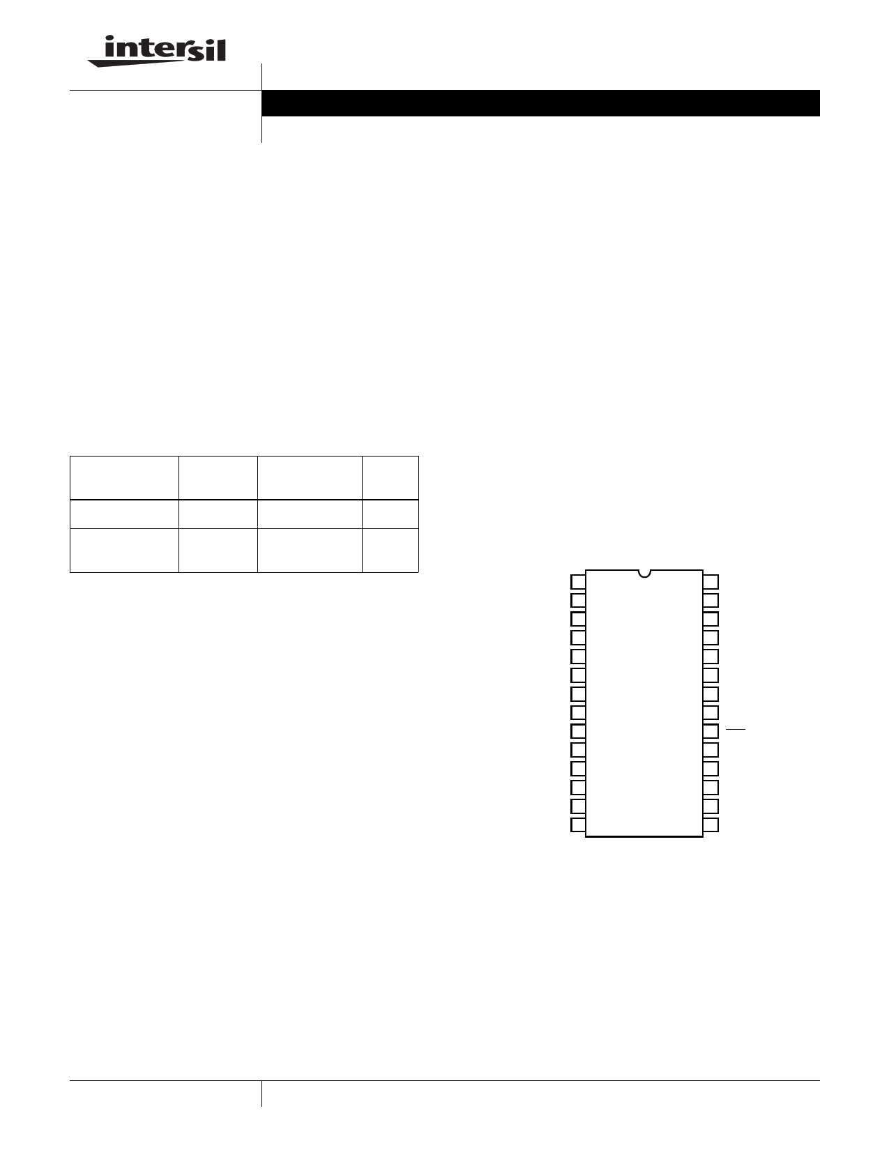
Pinout
HI5735 (SOIC)
TOP VIEW
D11 (MSB) 1
D10 2
D9 3
D8 4
D7 5
D6 6
D5 7
D4 8
D3 9
D2 10
D1 11
D0 (LSB) 12
NC 13
NC 14
28 DGND
27 AGND
26 REF OUT
25 CTRL OUT
24 CTRL IN
23 RSET
22 AVEE
21 IOUT
20 IOUT
19 ARTN
18 DVEE
17 DGND
16 DVCC
15 CLOCK
1 CAUTION: These devices are sensitive to electrostatic discharge; follow proper IC Handling Procedures.
1-888-INTERSIL or 321-724-7143 | Intersil (and design) is a registered trademark of Intersil Americas Inc.
Copyright Harris Corporation 1998. Copyright Intersil Americas Inc. 2003, 2004. All Rights Reserved
All other trademarks mentioned are the property of their respective owners.
1 page 
Timing Diagrams
CLK
D11-D0
IOUT
HI5735
50%
±1/2 LSB ERROR BAND
V GLITCH AREA = 1/2 (H x W)
HEIGHT (H)
WIDTH (W)
t (ps)
tPD tSETT
FIGURE 1. FULL SCALE SETTLING TIME DIAGRAM
FIGURE 2. PEAK GLITCH AREA (SINGLET) MEASUREMENT
METHOD
CLK
D11-D0
IOUT
tPW1
tPW2
tSU tSU tSU
tHLD
tHLD
tHLD
50%
tPD
tPD tPD
FIGURE 3. PROPAGATION DELAY, SETUP TIME, HOLD TIME AND MINIMUM PULSE WIDTH DIAGRAM
5
5 Page 
HI5735
Small Outline Plastic Packages (SOIC)
N
INDEX
AREA
E
-B-
H
0.25(0.010) M B M
123
-A-
D
SEATING PLANE
A
L
h x 45o
-C-
e A1
B
0.25(0.010) M C A M B S
α
0.10(0.004)
C
NOTES:
1. Symbols are defined in the “MO Series Symbol List” in Section 2.2
of Publication Number 95.
2. Dimensioning and tolerancing per ANSI Y14.5M-1982.
3. Dimension “D” does not include mold flash, protrusions or gate
burrs. Mold flash, protrusion and gate burrs shall not exceed
0.15mm (0.006 inch) per side.
4. Dimension “E” does not include interlead flash or protrusions. In-
terlead flash and protrusions shall not exceed 0.25mm (0.010
inch) per side.
5. The chamfer on the body is optional. If it is not present, a visual
index feature must be located within the crosshatched area.
6. “L” is the length of terminal for soldering to a substrate.
7. “N” is the number of terminal positions.
8. Terminal numbers are shown for reference only.
9. The lead width “B”, as measured 0.36mm (0.014 inch) or greater
above the seating plane, shall not exceed a maximum value of
0.61mm (0.024 inch)
10. Controlling dimension: MILLIMETER. Converted inch dimen-
sions are not necessarily exact.
M28.3 (JEDEC MS-013-AE ISSUE C)
28 LEAD WIDE BODY SMALL OUTLINE PLASTIC PACKAGE
INCHES
MILLIMETERS
SYMBOL MIN MAX MIN MAX NOTES
A
0.0926 0.1043 2.35
2.65
-
A1
0.0040 0.0118 0.10
0.30
-
B
0.013 0.0200 0.33
0.51
9
C
0.0091 0.0125 0.23
0.32
-
D 0.6969 0.7125 17.70 18.10
3
E
0.2914 0.2992 7.40
7.60
4
e 0.05 BSC
1.27 BSC
-
H 0.394 0.419 10.00 10.65
-
h 0.01 0.029 0.25 0.75 5
L
0.016 0.050 0.40
1.27
6
N 28
28 7
α 0o 8o 0o 8o -
Rev. 0 12/93
All Intersil U.S. products are manufactured, assembled and tested utilizing ISO9000 quality systems.
Intersil Corporation’s quality certifications can be viewed at www.intersil.com/design/quality
Intersil products are sold by description only. Intersil Corporation reserves the right to make changes in circuit design, software and/or specifications at any time without
notice. Accordingly, the reader is cautioned to verify that data sheets are current before placing orders. Information furnished by Intersil is believed to be accurate and
reliable. However, no responsibility is assumed by Intersil or its subsidiaries for its use; nor for any infringements of patents or other rights of third parties which may result
from its use. No license is granted by implication or otherwise under any patent or patent rights of Intersil or its subsidiaries.
For information regarding Intersil Corporation and its products, see www.intersil.com
11
11 Page | ||
| Páginas | Total 11 Páginas | |
| PDF Descargar | [ Datasheet HI5735.PDF ] | |
Hoja de datos destacado
| Número de pieza | Descripción | Fabricantes |
| HI5731 | A/D Converter | Intersil Corporation |
| HI5735 | A/D Converter | Intersil Corporation |
| Número de pieza | Descripción | Fabricantes |
| SLA6805M | High Voltage 3 phase Motor Driver IC. |
Sanken |
| SDC1742 | 12- and 14-Bit Hybrid Synchro / Resolver-to-Digital Converters. |
Analog Devices |
|
DataSheet.es es una pagina web que funciona como un repositorio de manuales o hoja de datos de muchos de los productos más populares, |
| DataSheet.es | 2020 | Privacy Policy | Contacto | Buscar |