|
|
|
PDF HMC627LP5 Data sheet ( Hoja de datos )
| Número de pieza | HMC627LP5 | |
| Descripción | LSB GaAs MMIC 6-BIT DIGITAL VARIABLE GAIN AMPLIFIER | |
| Fabricantes | Hittite Microwave Corporation | |
| Logotipo | ||
Hay una vista previa y un enlace de descarga de HMC627LP5 (archivo pdf) en la parte inferior de esta página. Total 10 Páginas | ||
|
No Preview Available !
www.DataSheet4U.com
HMC627LP5 / 627LP5E
v00.0707
0.5 dB LSB GaAs MMIC 6-BIT DIGITAL
VARIABLE GAIN AMPLIFIER, DC - 1 GHz
14
Typical Applications
The HMC627LP5(E) is ideal for:
• Cellular/3G Infrastructure
• WiBro / WiMAX / 4G
• Microwave Radio & VSAT
• Test Equipment and Sensors
• IF & RF Applications
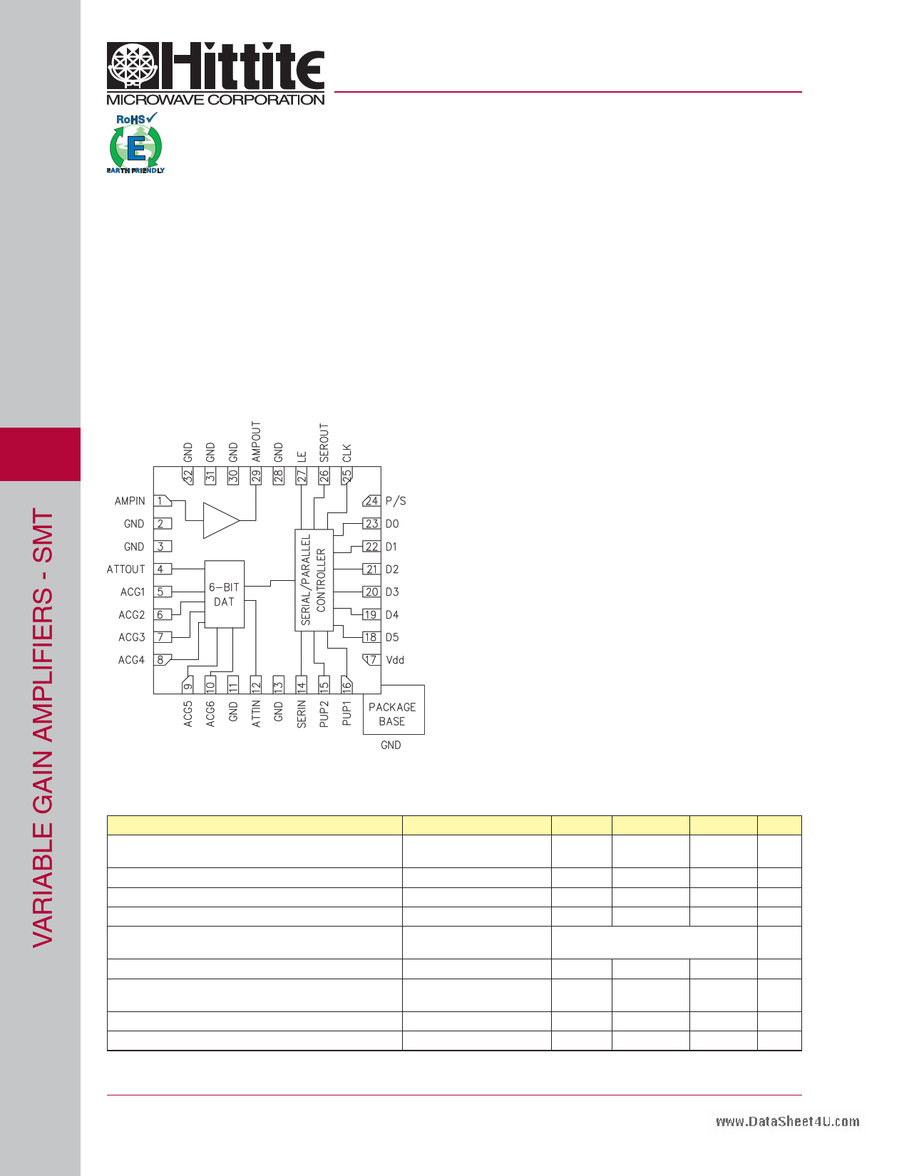
Functional Diagram
Features
-11.5 to 20 dB Gain Control in 0.5 dB Steps
High Output IP3: +36 dBm
TTL/CMOS Compatible Serial or Parallel Control
±0.25 dB Typical Gain Step Error
Single +5V Supply
Compact 5x5mm SMT Package
General Description
The HMC627LP5(E) is a digitally controlled variable
gain amplifier which operates from DC to 1 GHz,
and can be programmed to provide anywhere from
11.5 dB attenuation, to 20 dB of gain, in 0.5 dB steps.
The HMC627LP5(E) delivers noise figure of 4.3 dB
in its maximum gain state, with output IP3 of up to
+36 dBm in any state. The dual mode gain control
interface accepts either three wire serial input or 6
bit parallel word. The HMC627LP5(E) also features a
user selectable power up state and a serial output for
cascading other Hittite serially controlled components.
The HMC627LP5(E) is housed in a RoHS compliant
5x5 mm QFN leadless package, and requires no
external matching components.
Electrical Specifications, TA = +25° C, Vdd = +5V, Vs= +5V
Parameter
Frequency
Min.
Typ.
Max.
Gain (Maximum Gain State)
DC - 0.5 GHz
0.5 - 1.0 GHZ
18 20
15 17.5
Gain Control Range
31.5
Input Return Loss
DC - 1.0 GHz
17
Output Return Loss
DC - 1.0 GHz
12
Gain Accuracy: (Referenced to Maximum Gain State)
All Gain States
DC - 0.8 GHz
0.8 - 1.0 GHZ
± (0.10 + 5% of Gain Setting) Max.
± (0.30 + 3% of Gain Setting) Max.
Output Power for 1 dB Compression
DC - 1.0 GHz
16 20
Output Third Order Intercept Point
(Two-Tone Input Power= 0 dBm Each Tone)
DC - 1.0 GHz
36
Noise Figure
DC - 1.0 GHz
4.3
Supply Current (Idd)
DC - 1.0 GHz
90
Units
dB
dB
dB
dB
dB
dBm
dBm
dB
mA
14 - 20
For price, delivery, and to place orders, please contact Hittite Microwave Corporation:
20 Alpha Road, Chelmsford, MA 01824 Phone: 978-250-3343 Fax: 978-250-3373
Order On-line at www.hittite.com
1 page 
www.DataSheet4U.com
v00.0707
HMC627LP5 / 627LP5E
0.5 dB LSB GaAs MMIC 6-BIT DIGITAL
VARIABLE GAIN AMPLIFIER, DC - 1 GHz
Power-Up States
Using the Parallel PUP truth table the attenuator can
be turned on at a specific attenuation state. By using
the PUP1 and PUP2 line four different attenuation
states can be selected. It can also be used in the
Direct Parallel Mode using the Control Voltage Inputs
to select attenuation values.
Parallel PUP Truth Table
Gain Relative to
P/S
LE
PUP2
PUP1
Maximum Gain
0000
-31.5
0010
-24
0001
-16
0011
-8
0 1 X X -0.5 to -31.5 dB
Note: Power-Up with LE= 1 provides normal parallel operation
with D0 - D5, and PUP1 and PUP2 are not active.
14
Absolute Maximum Ratings
RF Input Power [1]
Digital Inputs (Reset, Shift Clock,
Latch Enable & Serial Input)
Bias Voltage (Vdd)
Collector Bias Voltage (Vcc)
Channel Temperature
Continuous Pdiss (T = 85 °C)
(derate 9 mW/°C above 85 °C) [1]
Thermal Resistance
Storage Temperature
Operating Temperature
[1] At max gain settling
11.5 dBm (T = +85 °C)
-1.5V to (Vdd +1.5V) Vdc
5.6 Vdc
5.5 Vdc
150 °C
0.593 W
110 °C/W
-65 to +150 °C
-40 to +85 °C
Bias Voltage
Vdd (V)
+5.0
Vs (V)
+5.0
Idd (Typ.) (mA)
2
Is (mA)
88
ELECTROSTATIC SENSITIVE DEVICE
OBSERVE HANDLING PRECAUTIONS
Truth Table
Control Voltage Input
Gain
Relative to
D5 D4 D3 D2 D1 D0 Maximum
Gain
High High High High High High
0 dB
High High High High High Low
-0.5 dB
High High High High Low High
-1 dB
High High High Low High High
-2 dB
High High Low High High High
-4 dB
High Low High High High High
-8 dB
Low High High High High High
-16 dB
Low Low Low Low Low Low -31.5 dB
Any combination of the above states will provide a reduction in
gain approximately equal to the sum of the bits selected.
TTL/CMOS Control Voltage
State
Low
High
Vdd= +3V or +5V
0 to 0.8V
2.0V to Vdd
14 - 24
For price, delivery, and to place orders, please contact Hittite Microwave Corporation:
20 Alpha Road, Chelmsford, MA 01824 Phone: 978-250-3343 Fax: 978-250-3373
Order On-line at www.hittite.com
5 Page | ||
| Páginas | Total 10 Páginas | |
| PDF Descargar | [ Datasheet HMC627LP5.PDF ] | |
Hoja de datos destacado
| Número de pieza | Descripción | Fabricantes |
| HMC627LP5 | LSB GaAs MMIC 6-BIT DIGITAL VARIABLE GAIN AMPLIFIER | Hittite Microwave Corporation |
| HMC627LP5E | LSB GaAs MMIC 6-BIT DIGITAL VARIABLE GAIN AMPLIFIER | Hittite Microwave Corporation |
| Número de pieza | Descripción | Fabricantes |
| SLA6805M | High Voltage 3 phase Motor Driver IC. |
Sanken |
| SDC1742 | 12- and 14-Bit Hybrid Synchro / Resolver-to-Digital Converters. |
Analog Devices |
|
DataSheet.es es una pagina web que funciona como un repositorio de manuales o hoja de datos de muchos de los productos más populares, |
| DataSheet.es | 2020 | Privacy Policy | Contacto | Buscar |