|
|
|
PDF NTB4302 Data sheet ( Hoja de datos )
| Número de pieza | NTB4302 | |
| Descripción | Power MOSFET ( Transistor ) | |
| Fabricantes | ON Semiconductor | |
| Logotipo | ||
Hay una vista previa y un enlace de descarga de NTB4302 (archivo pdf) en la parte inferior de esta página. Total 8 Páginas | ||
|
No Preview Available !
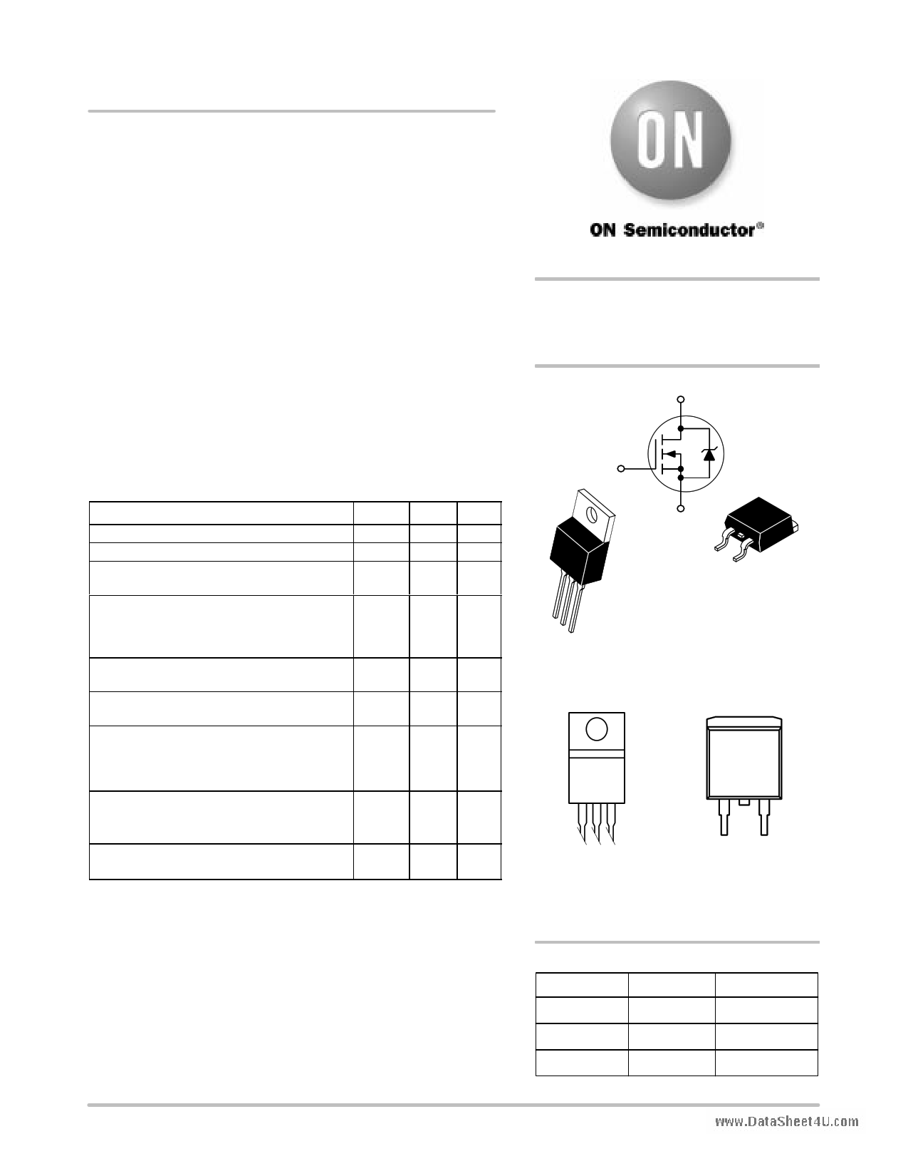
NTP4302, NTB4302
Power MOSFET
74 Amps, 30 Volts
N−Channel TO−220 and D2PAK
Features
• Low RDS(on)
• Higher Efficiency Extending Battery Life
• Diode Exhibits High Speed, Soft Recovery
• Avalanche Energy Specified
• IDSS Specified at Elevated Temperature
www.DataSheet4U.com
Typical Applications
• DC−DC Converters
• Low Voltage Motor Control
• Power Management in Portable and Battery Powered Products: Ie:
Computers, Printers, Cellular and Cordless Telephones, and PCMCIA
Cards
MAXIMUM RATINGS (TJ = 25°C unless otherwise noted)
Rating
Symbol Value Unit
Drain−to−Source Voltage
Drain−to−Gate Voltage (RGS = 10 MΩ)
Gate−to−Source Voltage
− Continuous
Drain Current
− Continuous @ TC = 25°C
− Continuous @ TC = 100°C
− Single Pulse (tpv10 µs)
Total Power Dissipation @ TC = 25°C
Derate above 25°C
Operating and Storage Temperature Range
VDSS
VDGR
VGS
30
30
"20
Vdc
Vdc
Vdc
ID
ID
IDM
PD
TJ, Tstg
74
47
175
80
0.66
−55 to
+150
Adc
Apk
W
W/°C
°C
Single Pulse Drain−to−Source Avalanche
Energy − Starting TJ = 25°C
(VDD = 30 Vdc, VGS = 10 Vdc, L = 5.0 mH
IL(pk) = 17 A, VDS = 30 Vdc, RG = 25 Ω)
EAS 722 mJ
Thermal Resistance
− Junction−to−Case
− Junction−to−Ambient (Note 1)
RθJC
RθJA
°C/W
1.55
70
Maximum Lead Temperature for Soldering
Purposes, 1/8″ from case for 10 seconds
TL 260 °C
1. When surface mounted to an FR4 Board using minimum recommended Pad
Size, (Cu Area 0.412 in2).
2. Current limited by internal lead wires.
http://onsemi.com
74 AMPERES
30 VOLTS
RDS(on) = 9.3 mΩ Max
N−Channel
D
G
4
S
4
12
3
1
2
3
TO−220AB
CASE 221A
STYLE 5
D2PAK
CASE 418AA
STYLE 2
MARKING DIAGRAMS
& PIN ASSIGNMENTS
4
Drain
4
Drain
NTx4302
LLYWW
NTx4302
LLYWW
1
Gate
3
Source
1 23
Gate Drain Source
2
Drain
x
NTx4302
LL
Y
WW
= P or B
= Device Code
= Location Code
= Year
= Work Week
ORDERING INFORMATION
Device
Package
Shipping
NTP4302
NTB4302
TO−220AB
D2PAK
50 Units/Rail
50 Units/Rail
NTB4302T4
D2PAK
800/Tape & Reel
© Semiconductor Components Industries, LLC, 2003
October, 2003 − Rev. 1
1
Publication Order Number:
NTP4302/D
1 page 
1.00
D = 0.5
0.2
0.1
0.10 0.05
0.02
0.01
SINGLE PULSE
0.01
www.DataSheet4U.com 1.0E−05
1.0E−04
NTP4302, NTB4302
SAFE OPERATING AREA
P(pk)
t1
t2
DUTY CYCLE, D = t1/t2
1.0E−03
1.0E−02
t, TIME (s)
1.0E−01
Figure 13. Thermal Response
RθJC(t) = r(t) RθJC
D CURVES APPLY FOR POWER
PULSE TRAIN SHOWN
READ TIME AT t1
TJ(pk) − TC = P(pk) RθJC(t)
1.0E+00
1.0E+01
di/dt
IS
trr
ta tb
TIME
tp 0.25 IS
IS
Figure 14. Diode Reverse Recovery Waveform
http://onsemi.com
5
5 Page | ||
| Páginas | Total 8 Páginas | |
| PDF Descargar | [ Datasheet NTB4302.PDF ] | |
Hoja de datos destacado
| Número de pieza | Descripción | Fabricantes |
| NTB4302 | Power MOSFET ( Transistor ) | ON Semiconductor |
| Número de pieza | Descripción | Fabricantes |
| SLA6805M | High Voltage 3 phase Motor Driver IC. |
Sanken |
| SDC1742 | 12- and 14-Bit Hybrid Synchro / Resolver-to-Digital Converters. |
Analog Devices |
|
DataSheet.es es una pagina web que funciona como un repositorio de manuales o hoja de datos de muchos de los productos más populares, |
| DataSheet.es | 2020 | Privacy Policy | Contacto | Buscar |