|
|
|
PDF SC4602A Data sheet ( Hoja de datos )
| Número de pieza | SC4602A | |
| Descripción | Step Down Controller | |
| Fabricantes | Semtech Corporation | |
| Logotipo | ||
Hay una vista previa y un enlace de descarga de SC4602A (archivo pdf) en la parte inferior de esta página. Total 18 Páginas | ||
|
No Preview Available !
POWER MANAGEMENT
Description
The SC4602A/B is a voltage mode step down (buck) regu-
lator controller that provides accurate high efficiency
power conversion from an input supply range of 2.75V
to 5.5V. A high level of integration reduces external com-
ponent count and makes it suitable for low voltage appli-
cations where cost, size and efficiency are critical.
The SC4602A/B drives external complementary power
MOSFETs; P-channel on the high side and N-channel on
www.DatatShheeetl4oUw.cosmide. The use of high side P-channel MOSFET
eliminates the need for an external charge pump and
simplifies the high side gate driver. Non-overlap protec-
tion is provided for the gate drive signals to prevent shoot
through of the MOSFET pair. Voltage drop across the P-
channel MOSFET during its conduction is sensed for
lossless short circuit current limiting.
A low power sleep mode can be achieved by forcing the
SYNC/SLEEP pin below 0.8V. A synchronous mode of op-
eration is activated as the SYNC/SLEEP pin is driven by
an external clock. The quiescent supply current in sleep
mode is typically lower than 10µA. A soft start (2.4ms for
the SC4602A and 1.2ms for the SC4602B) is internally
provided to prevent output voltage overshoot during start-
up. A 100% maximum duty cycle allows the SC4602A/B
to operate as a low dropout regulator in the event of a
low battery condition. The SC4602A/B has fixed switch-
ing frequency (300KHz for the SC4602A and 550KHz
for the SC4602B).
SC4602A/B
High Efficiency Synchronous,
Step Down Controller
Features
BICMOS Voltage mode PWM controller
2.75V to 5.5V Input voltage range
Output voltages as low as 0.8V
+/-1% Reference accuracy
Sleep Mode (Icc = 10µA typ)
Lossless short circuit current limiting
Combination pulse by pulse & hiccup mode current
limit
High efficiency synchronous switching
Up to 100% Duty cycle range
Synchronization to external clock
8-Pin MSOP surface mount package. Lead-free pack-
age available, fully WEEE and RoHS compliant
Applications
Distributed power system
RF power supply
Local microprocessor core power supplies
DSP and I/O power supplies
Battery powered applications
Servers and workstations
The SC4602A/B is an ideal choice for 3.3V, 5V or other
low input supply sytems. It’s available in a 8 pin MSOP
package.
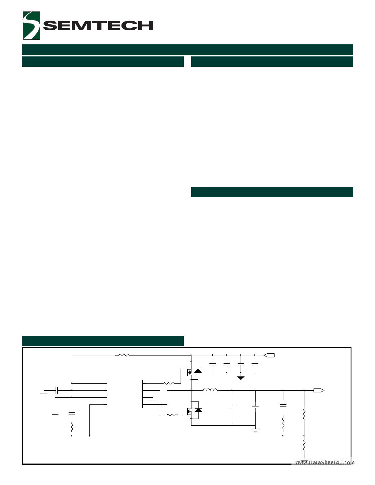
Typical Application Circuit
R15
1
M1
C3
4.7u
C1
470p
C2
6.8n
R1
5.11k
U1
1 VCC
PDRV 8
2 SY NC/SLEEP NDRV 7
3 COMP
GND 6
4 VSENSE
PHASE 5
SC4602B
R6
1.0
M2
R5
1.0
Vin = 2.75V ~ 5.5V
C10 C11 C12 C13
22u 22u 22u 22u
L1 Vo = 1.5V (as low as 0.8V )/6A
1.6u
C7
150u
C4
22u
C9
3.3n
R8
169
R7
4.64k
* External components can be modified to provide a VOUT as low as 0.8V.
R9
5.36k
Revision: January 20, 2006
1
www.semtech.com
1 page 
SC4602A/B
POWER MANAGEMENT
Pin Configuration
Ordering Information
Top View
www.DataSheet4U.com
(8 Pin MSOP)
Part Number(1)
SC4602AIMSTR
SC4602AIMSTRT(2)
SC4602BIMSTR
SC4602BIMSTRT(2)
SC4602AEVB
SC4602BEVB
kHz Device
300 MSOP-8
550 MSOP-8
Evaluation Board
Pin Descriptions
VCC: Positive supply rail for the IC. Bypass this pin to
GND with a 0.1 to 4.7µF low ESL/ESR ceramic capaci-
tor.
GND: All voltages are measured with respect to this pin.
All bypass and timing capacitors connected to GND should
have leads as short and direct as possible.
SYNC/SLEEP: The oscillator of SC4602A and SC4602B
are set to 300kHz and 550kHz respectively when SYNC/
SLEEP is pulled and held above 2V. Synchronous mode
operation is activated as the SYNC/SLEEP is driven by an
external clock. The oscillator and PWM are designed to
provide practical operation to 450kHz for SC4602A and
to 700kHz for SC4602B when synchronized. Sleep mode
is invoked if SYNC/SLEEP is pulled and held below 0.8V
which can be accomplished by an external gate or tran-
sistor. Sleepmode supply current is 10µA typical.
VSENSE: This pin is the inverting input of the voltage
amplifier and serves as the output voltage feedback point
for the Buck converter. It senses the output voltage through
an external divider.
Notes:
(1) Only available in tape and reel packaging. A reel
contains 2500 devices.
(2) Lead free product. This product is fully WEEE and
RoHS compliant.
PHASE: This input is connected to the junction between
the two external power MOSFET transistors. The voltage
drop across the upper P-channel device is monitored by
PHASE during conduction and forms the current limit
comparator. Logic sets the PWM latch and terminates
the output pulse. The controller stops switching and goes
through a soft start sequence once the converter out-
put voltage drops below 68.75% its nominal voltage. This
prevents excess power dissipation in the PMOSFET dur-
ing a short circuit. The reverse current comparator senses
the drop across the lower N-channel MOSFET during its
conduction and disables the drive signal if a small posi-
tive voltage is present. To disable the overcurrent com-
parator, connect PHASE to VCC.
PDRV, NDRV: The PWM circuitry provides complemen-
tary drive signals to the output stages. Cross conduc-
tion of the external MOSFETS is prevented by monitoring
the voltage on the P-channel and N-channel driver pins
in conjunction with a time delay optimized for FET turn-
off characteristics.
COMP: This is the output of the voltage amplifier. The
voltage at this output is inverted internally and connected
to the non-inverting input of the PWM comparator. A lead-
lag network around the voltage amplifier compensates for
the two pole LC filter characteristic inherent to voltage mode
control and is required in order to optimize the dynamic
performance of the voltage mode control loop.
2006 Semtech Corp.
5
www.semtech.com
5 Page 
SC4602A/B
POWER MANAGEMENT
Applications Information (Cont.)
After the required inductor value is selected, the proper
selection of the core material is based on the peak in-
ductor current and efficiency requirements. The core
must be able to handle the peak inductor current IPEAK
without saturation and produce low core loss during the
high frequency operation.
IPEAK
= IOMAX
+
Ip −p
2
The power loss for the inductor includes its core loss and
www.DatacSohepept4eUr.cloomss. If possible, the winding resistance should
be minimized to reduce inductor’s copper loss. The core
loss can be found in the manufacturer’s datasheet. The
inductor’ copper loss can be estimated as follows:
PCOPPER
=
I2
LRMS
⋅ RWINDING
Where:
ILRMS is the RMS current in the inductor. This current can
be calculated as follows:
ILRMS = IOMAX ⋅
1+
1
3
⋅
∆I2
Output Capacitor Selection
Basically there are two major factors to consider in se-
lecting the type and quantity of the output capacitors.
The first one is the required ESR (Equivalent Series Re-
sistance) which should be low enough to reduce the volt-
age deviation from its nominal one during its load changes.
The second one is the required capacitance, which should
be high enough to hold up the output voltage. Before the
SC4602A/B regulates the inductor current to a new value
during a load transient, the output capacitor delivers all
the additional current needed by the load. The ESR and
ESL of the output capacitor, the loop parasitic inductance
between the output capacitor and the load combined
with inductor ripple current are all major contributors to
the output voltage ripple. Surface mount speciality poly-
mer aluminum electrolytic chip capacitors in UE series
from Panasonic provide low ESR and reduce the total
capacitance required for a fast transient response.
POSCAP from Sanyo is a solid electrolytic chip capacitor
which has a low ESR and good performance for high fre-
quency with a low profile and high capacitance. Above
mentioned capacitors are recommended to use in
SC4602A/B applications.
Input Capacitor Selection
The input capacitor selection is based on its ripple cur-
rent level, required capacitance and voltage rating. This
capacitor must be able to provide the ripple current by
the switching actions. For the continuous conduction
mode, the RMS value of the input capacitor can be cal-
culated from:
ICIN(RMS) = IOMAX ⋅
VO ⋅ (VI − VO )
V
2
I
This current gives the capacitor’s power loss as follows:
PCIN
=
I2
CIN( RMS )
⋅ RCIN(ESR)
This capacitor’s RMS loss can be a significant part of the
total loss in the converter and reduce the overall con-
verter efficiency. The input ripple voltage mainly depends
on the input capacitor’s ESR and its capacitance for a
given load, input voltage and output voltage. Assuming
that the input current of the converter is constant, the
required input capacitance for a given voltage ripple can
be calculated by:
CIN
= IOMAX
⋅
fs ⋅ (∆VI
D ⋅ (1− D)
− IOMAX ⋅ RCIN(ESR) )
Where:
DDV=I =VOth/VeI
, duty
given
ratio
input
and
voltage
ripple.
Because the input capacitor is exposed to the large surge
current, attention is needed for the input capacitor. If
tantalum capacitors are used at the input side of the
converter, one needs to ensure that the RMS and surge
ratings are not exceeded. For generic tantalum capaci-
tors, it is wise to derate their voltage ratings at a ratio of
2 to protect these input capacitors.
Power Mosfet Selection
The SC4602A/B can drive a P-MOSFET at the high side
and an N-MOSFET synchronous rectifier at the low side.
The use of the high side P-MOSFET eliminates the need
for an external charge pump and simplifies the high side
gate driver circuit.
2006 Semtech Corp.
11
www.semtech.com
11 Page | ||
| Páginas | Total 18 Páginas | |
| PDF Descargar | [ Datasheet SC4602A.PDF ] | |
Hoja de datos destacado
| Número de pieza | Descripción | Fabricantes |
| SC4602A | Step Down Controller | Semtech Corporation |
| SC4602B | Step Down Controller | Semtech Corporation |
| Número de pieza | Descripción | Fabricantes |
| SLA6805M | High Voltage 3 phase Motor Driver IC. |
Sanken |
| SDC1742 | 12- and 14-Bit Hybrid Synchro / Resolver-to-Digital Converters. |
Analog Devices |
|
DataSheet.es es una pagina web que funciona como un repositorio de manuales o hoja de datos de muchos de los productos más populares, |
| DataSheet.es | 2020 | Privacy Policy | Contacto | Buscar |