|
|
|
PDF HGTP3N60C3D Data sheet ( Hoja de datos )
| Número de pieza | HGTP3N60C3D | |
| Descripción | UFS Series N-Channel IGBT | |
| Fabricantes | Harris Corporation | |
| Logotipo | ||
Hay una vista previa y un enlace de descarga de HGTP3N60C3D (archivo pdf) en la parte inferior de esta página. Total 7 Páginas | ||
|
No Preview Available !
HGTP3N60C3D, HGT1S3N60C3D,
SEMICONDUCTOR
HGT1S3N60C3DS
www.DataSheet4U.com
January 1997
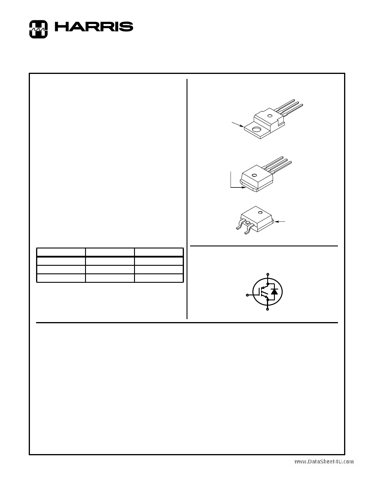
6A, 600V, UFS Series N-Channel IGBT
with Anti-Parallel Hyperfast Diodes
Features
• 6A, 600V at TC = 25oC
• 600V Switching SOA Capability
• Typical Fall Time . . . . . . . . . . . . . . 130ns at TJ = 150oC
• Short Circuit Rating
• Low Conduction Loss
• Hyperfast Anti-Parallel Diode
Packaging
JEDEC TO-220AB
COLLECTOR (FLANGE)
EMITTER
COLLECTOR
GATE
Description
The HGTP3N60C3D, HGT1S3N60C3D, and HGT1S3N60C3DS
are MOS gated high voltage switching devices combining the
best features of MOSFETs and bipolar transistors. These
devices have the high input impedance of a MOSFET and the
low on-state conduction loss of a bipolar transistor. The much
lower on-state voltage drop varies only moderately between
25oC and 150oC. The IGBT used is the development type
TA49113. The diode used in anti-parallel with the IGBT is the
development type TA49055.
The IGBT is ideal for many high voltage switching applications
operating at moderate frequencies where low conduction losses
are essential.
PACKAGING AVAILABILITY
JEDEC TO-262AA
EMITTER
COLLECTOR
(FLANGE)
COLLECTOR
GATE
JEDEC TO-263AB
GATE
EMITTER
MA
COLLECTOR
(FLANGE)
PART NUMBER
HGTP3N60C3D
HGT1S3N60C3D
HGT1S3N60C3DS
PACKAGE
TO-220AB
TO-262AA
TO-263AB
BRAND
G3N60C3D
G3N60C3D
G3N60C3D
Terminal Diagram
N-CHANNEL ENHANCEMENT MODE
C
NOTE: When ordering, use the entire part number. Add the suffix 9A to
obtain the TO-263AB variant in tape and reel, i.e. HGT1S3N60C3DS9A.
G
Formerly Developmental Type TA49119.
E
Absolute Maximum Ratings TC = 25oC, Unless Otherwise Specified
Collector-Emitter Voltage . . . . . . . . . . . . . . . . . . . . . . . . . . . . . . . . . . . . . . . . . . . .BVCES
Collector Current Continuous
At
At
TC
TC
=
=
25oC .
110oC
.
.
.
.
.
.
.
.
.
.
.
.
.
.
.
.
.
.
.
.
.
.
.
.
.
.
.
.
.
.
.
.
.
.
.
.
.
.
.
.
.
.
.
.
.
.
.
.
.
.
.
.
.
.
.
.
.
.
.
.
.
.
.
.
.
.
.
.
.
.
.
.
.
.
.
.
.
.
.
.
.
.
.
.
.
.
.
.
.
.
.
.
.
.
.
.
.
.
.
.
.
.
.
.
. IC25
IC110
Collector Current Pulsed (Note 1) . . . . . . . . . . . . . . . . . . . . . . . . . . . . . . . . . . . . . . . . ICM
Gate-Emitter Voltage Continuous . . . . . . . . . . . . . . . . . . . . . . . . . . . . . . . . . . . . . . . VGES
Gate-Emitter Voltage Pulsed. . . . . . . . . . . . . . . . . . . . .
Switching Safe Operating Area at TJ = 150oC, Fig. 14.
.
.
.
.
.
.
.
.
.
.
.
.
.
.
.
.
.
.
.
.
.
.
.
.
.
.
.
.
.
.
.
.
.
.
.
.
.
.
.
.
.
.
VGEM
SSOA
Power Dissipation Total at TC = 25oC . . . . . . . . . . . . . . . . . . . . . . . . . . . . . . . . . . . . . PD
Power Dissipation Derating TC > 25oC. . . . . . . . . . . . . . . . . . . . . . . . . . . . . . . . . . . . . . .
Operating and Storage Junction Temperature Range . . . . . . . . . . . . . . . . . . . . TJ, TSTG
Maximum Lead Temperature for Soldering. . . . . . . . . . . . . . . . . . . . . . . . . . . . . . . . . . TL
Short Circuit Withstand Time (Note 2) at VGE = 10V, Fig 6 . . . . . . . . . . . . . . . . . . . . .tSC
NOTES:
1. Repetitive Rating: Pulse width limited by maximum junction temperature.
2. VCE(PK) = 360V, TJ = 125oC, RGE = 82Ω.
HGTP3N60C3D, HGT1S3N60C3D
HGT1S3N60C3DS
600
6
3
24
±20
±30
18A at 480V
33
0.27
-40 to 150
260
8
UNITS
V
A
A
A
V
V
W
W/ oC
oC
oC
µs
CAUTION: These devices are sensitive to electrostatic discharge. Users should follow proper ESD Handling Procedures.
Copyright © Harris Corporation 1997
3-9
File Number 4140.1
1 page 
HGTP3N60C3D, HGT1S3N60C3D, HGT1S3N60C3DS
Typical Performance Curves (Continued)
www.DataSheet4U.com
200
100
TJ = 150oC, TC = 75oC
RG = 82Ω, L = 1mH
fMAX1 = 0.05/(tD(OFF)I + tD(ON)I)
fMAX2 = (PD - PC)/(EON + EOFF)
PD = ALLOWABLE DISSIPATION
PC = CONDUCTION DISSIPATION
(DUTY FACTOR = 50%)
RθJC = 3.75oC/W
10
1
2
3
VGE = 15V
VGE = 10V
4 56
ICE, COLLECTOR-EMITTER CURRENT (A)
FIGURE 13. OPERATING FREQUENCY AS A FUNCTION OF
COLLECTOR-EMITTER CURRENT
20 TJ = 150oC, VGE = 15V, RG = 82Ω, L = 1mH
18
16
14
12
10
8
6
4
2
0
0 100 200 300 400 500 600
VCE(PK), COLLECTOR-TO-EMITTER VOLTAGE (V)
FIGURE 14. MINIMUM SWITCHING SAFE OPERATING AREA
500
FREQUENCY = 1MHz
400 CIES
300
200
100
0
0
COES
CRES
5 10 15 20
VCE, COLLECTOR-TO-EMITTER VOLTAGE (V)
25
FIGURE 15. CAPACITANCE AS A FUNCTION OF COLLECTOR-
EMITTER VOLTAGE
600 15
480 12
360 9
VCE = 600V
VCE = 400V
240
VCE = 200V
6
IG REF = 1.060mA
120
RL = 200Ω
3
TC = 25oC
00
0 2 4 6 8 10 12 14
QG, GATE CHARGE (nC)
FIGURE 16. GATE CHARGE WAVEFORMS
100
0.5
0.2
10-1 0.1
0.05
0.02
0.01
SINGLE PULSE
10-2
10-5
10-4
t1
PD
t2
DUTY FACTOR, D = t1 / t2
PEAK TJ = (PD X ZθJC X RθJC) + TC
10-3
10-2
10-1
100
101
t1, RECTANGULAR PULSE DURATION (s)
FIGURE 17. IGBT NORMALIZED TRANSIENT THERMAL IMPEDANCE, JUNCTION TO CASE
3-13
5 Page | ||
| Páginas | Total 7 Páginas | |
| PDF Descargar | [ Datasheet HGTP3N60C3D.PDF ] | |
Hoja de datos destacado
| Número de pieza | Descripción | Fabricantes |
| HGTP3N60C3 | 6A/ 600V/ UFS Series N-Channel IGBTs | Intersil Corporation |
| HGTP3N60C3D | 6A/ 600V/ UFS Series N-Channel IGBT with Anti-Parallel Hyperfast Diodes | Fairchild Semiconductor |
| HGTP3N60C3D | 6A/ 600V/ UFS Series N-Channel IGBT with Anti-Parallel Hyperfast Diodes | Intersil Corporation |
| HGTP3N60C3D | UFS Series N-Channel IGBT | Harris Corporation |
| Número de pieza | Descripción | Fabricantes |
| SLA6805M | High Voltage 3 phase Motor Driver IC. |
Sanken |
| SDC1742 | 12- and 14-Bit Hybrid Synchro / Resolver-to-Digital Converters. |
Analog Devices |
|
DataSheet.es es una pagina web que funciona como un repositorio de manuales o hoja de datos de muchos de los productos más populares, |
| DataSheet.es | 2020 | Privacy Policy | Contacto | Buscar |