|
|
|
PDF NJW1165 Data sheet ( Hoja de datos )
| Número de pieza | NJW1165 | |
| Descripción | AUDIO PROCESSOR | |
| Fabricantes | New Japan Radio | |
| Logotipo | ||
Hay una vista previa y un enlace de descarga de NJW1165 (archivo pdf) en la parte inferior de esta página. Total 25 Páginas | ||
|
No Preview Available !
NJW1165
AUDIO PROCESSOR
www.datasheet4u.com
s GENERAL DESCRIPTION
The NJW1165 is an audio processor. It includes all of
functions processing audio signal for TV, such as tone
control, balance, volume, mute, NJRC original surround, and
AGC functions.
The NJRC original surround system reproduces natural
surround sound and clear vocal orientation.
All of internal status and variables are controlled by I2C
BUS interface.
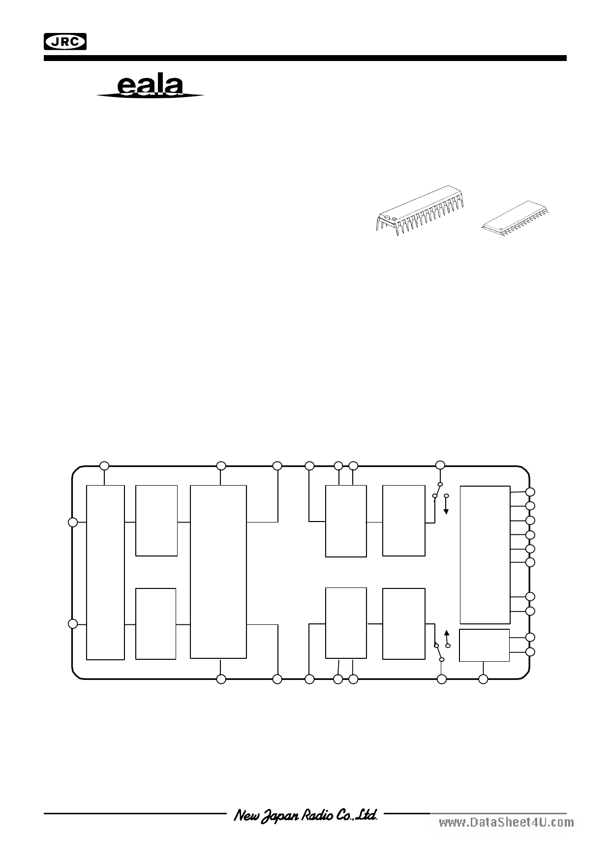
s PACKAGE OUTLINE
NJW1165L
NJW1165M
s FEATURES
q Operating Voltage
7.5 to 13V
q I2C BUS Interface
q eala (NJRC Original Surround)
q AGC Circuit (It reduces volume difference among input sources.)
q Simulated Surround
q Bi-CMOS Technology
q Package Outline
SDIP30, SDMP30
s BLOCK DIAGRAM
VOL1
AGC
e ala
&
Sim ulated
Surround
VOL1
TONE
VOL2
TONE
VOL2
I2C Bus
Interface
Bias
-1-
1 page 
NJW1165
s I2C BUS BLOCK CHARACTERISTICS (SDA, SCL)
PARAMETER
SYMBOL
High Level Input Voltage
www.datLasohweeLt4euv.ceolmInput Voltage
High Level Input Current
Low Level Input Current
Low Level Output Voltage (3mA at SDA pin)
Maximum Output Current
Maximum Clock Frequency
Data Change Minimum Waiting Time
Data Transfer Start Minimum Waiting Time
Low Level Clock Pulse Width
High Level Clock Pulse Width
Minimum Start Preparation Waiting Time
Minimum Data Hold Time
Minimum Data Preparation Time
Rise Time
Fall Time
Minimum Stop Preparation Waiting Time
VIH
VIL
IIH
IIL
VOL
IOL
fSCL
tBUF
tHD:STA
tLOW
tHIGH
tSU:STA
tHD:DAT
tSU:DAT
tR
tF
tSU:STO
MIN.
2.5
0
-
-
0
-3.0
-
4.7
4.0
4.7
4.0
4.7
0
250
-
-
4.0
I2C BUS Load Condition:
Pull up resistance 4kΩ (Connected to +5V)
Load capacitance 200pF (Connected to GND)
TYP.
-
-
-
-
-
-
-
-
-
-
-
-
-
-
-
-
-
MAX.
5.0
1.5
10
10
0.4
-
100
-
-
-
-
-
3.45
-
1.0
300
-
UNIT
V
V
µA
µA
V
mA
kHz
µs
µs
µs
µs
µs
µs
ns
µs
ns
µs
SDA
tBUF
SCL
tR
tHD:STA tLOW
PS
tF
tHD:DAT
tHIGH
tSU:DAT
tHD:STA
tSU:STA
Sr
tSU:STO
P
-5-
5 Page 
NJW1165
s APPLICATION NOTE
1. AGC (Auto Gain Control) Circuit
AGC circuit adjusts the input signal level with Boost/Attenuate circuit. AGC boost the low input signal level
and attenuate high input signal level automatically.
www.datasheTeht4eu.cAoGmC flat levels (150mV, 300mV, 400mV and 540mV) are selectable via I2C bus. (Refer to the following
figure.)
AGC Control
V+=9V, Vin(Ach+Bch), f=1kHz, Vo(Ach)OUTPUT
Rg=600Ω, Ta=25oC
1 540mV
0.1 AGC ON
400mV
300mV
150mV
0.01
AGC OFF
Attack-Recovery
0.001
0.001
0.01 0.1
1
Input Voltage [Vrms]
Ra=4kΩ
Ir=0.5µA
9pin
Ca
Rb=8kΩ
11pin
12pin
Cb
Smoothing circuit of Attenuate
Smoothing circuit of Boost
Attack and recovery time in the attenuation processing depends on external part Ca, and it in the boost
processing depends on external part Cb. They become longer as the capacity bigger and become shorter as
it gets smaller. (Recommendation value: Ca=1µF, Cb=4.7µF)
Reducing the capacity of Ca may cause the distortion. As for Cb, since it serves as the click noise
prevention, reducing the capacity may cause the click noise upon volume changing.
- 11 -
11 Page | ||
| Páginas | Total 25 Páginas | |
| PDF Descargar | [ Datasheet NJW1165.PDF ] | |
Hoja de datos destacado
| Número de pieza | Descripción | Fabricantes |
| NJW1160 | AUDIO PROCESSOR | New Japan Radio |
| NJW1161 | AUDIO PROCESSOR | New Japan Radio |
| NJW1163 | AUDIO PROCESSOR | New Japan Radio |
| NJW1163A | AUDIO PROCESSOR | New Japan Radio |
| Número de pieza | Descripción | Fabricantes |
| SLA6805M | High Voltage 3 phase Motor Driver IC. |
Sanken |
| SDC1742 | 12- and 14-Bit Hybrid Synchro / Resolver-to-Digital Converters. |
Analog Devices |
|
DataSheet.es es una pagina web que funciona como un repositorio de manuales o hoja de datos de muchos de los productos más populares, |
| DataSheet.es | 2020 | Privacy Policy | Contacto | Buscar |