|
|
|
PDF AKD4644-B Data sheet ( Hoja de datos )
| Número de pieza | AKD4644-B | |
| Descripción | Stereo CODEC | |
| Fabricantes | Asahi Kasei Microsystems | |
| Logotipo | ||
Hay una vista previa y un enlace de descarga de AKD4644-B (archivo pdf) en la parte inferior de esta página. Total 30 Páginas | ||
|
No Preview Available !
ASAHI KASEI
www.DataSheet4U.com
[AKD4644-B]
AKD4644-B
AK4644 Evaluation board Rev.0
GENERAL DESCRIPTION
AKD4644-B is an evaluation board for the AK4644, Stereo CODEC with built-in MIC/HP/RCV amplifier.
The AKD4644-B can evaluate A/D converter and D/A converter separately in addition to loop-back mode
(A/D → D/A). The AKD4644-B also has the digital audio interface and can achieve the interface with
digital audio systems via opt-connector.
Ordering guide
AKD4644-B
--- Evaluation board for AK4644
(Cable for connecting with printer port of IBM-AT compatible PC and control
software are packed with this. This control software does not operate on Windows
NT.)
FUNCTION
• DIT/DIR with optical input/output
• 10pin Header for serial control mode
• Mini-jack for external Stereo Speaker
• On-board Stereo Class-D Speaker Amplifier (AK7830)
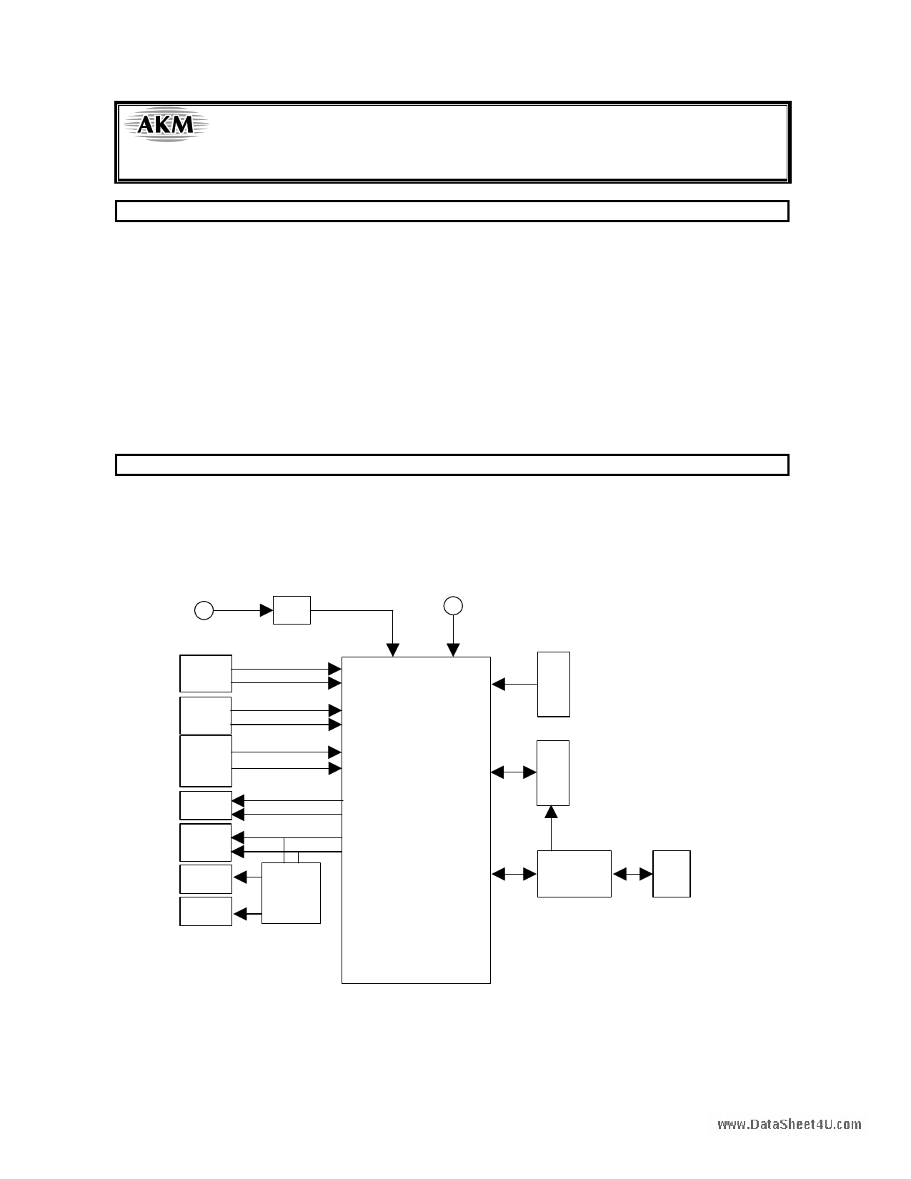
5V Regulator
GND
3.3V
LIN1/
RIN1
LIN2/
RIN2
MIN/
LIN3/
RIN3
HP
LOUT/
ROUT
SPL
SPR
AK7830
AK4644
Control Data
10pin Header
DSP
10pin Header
AK4114
Opt In
Opt Out
<KM082800>
Figure 1. AKD4644-B Block Diagram
* Circuit diagram and PCB layout are attached at the end of this manual
-1-
2006 / 03
1 page 
ASAHI KASEI
[AKD4644-B]
www.DataSheet4U.com
Serial Control
The AK4644 can be controlled via the printer port (parallel port) of IBM-AT compatible PC. Connect PORT4
(CTRL) with PC by 10 wire flat cable packed with the AKD4644. When I2C bus mode is used, PORT4 should be
directly connected to the I2C bus on the system. JP13,14 and 15 should be set to I2C bus mode to control the
AK7830.
PC
10 wire
flat cable
Connect
CSN
SCL/CCLK
SDA/CDTI
10pin
Connector
AKD4644-B
10pin Header
Figure 2. Connect of 10 wire flat cable
(1) 3-wire Serial Control Mode <Default>
The jumper pins should be set to the following.
JP14
CAD0
JP13
I2C_SEL
JP15
SDA
(2) I2C-bus Control Mode
The jumper pins should be set to the following.
(2-1) In case of using CAD0=0 (device address bits).
I2C 3-wire
JP14
CAD0
JP13
I2C_SEL
JP15
SDA
(2-2) In case of using CAD0=1 (device address bits).
I2C 3-wire
JP14
CAD0
JP13
I2C_SEL
JP15
SDA
I2C 3-wire
<KM082800>
-5-
2006 / 03
5 Page 
ASAHI KASEI
[AKD4644-B]
www.DataSheet4U.com
4. [SAVE] and [OPEN]
4-1. [SAVE]
All of current register setting values displayed on the main window are saved to the file. The extension of file name is
“akr”.
<Operation flow>
(1) Click [SAVE] Button.
(2) Set the file name and click [SAVE] Button. The extension of file name is “akr”.
4-2. [OPEN]
The register setting values saved by [SAVE] are written to the AK4644. The file type is the same as [SAVE].
<Operation flow>
(1) Click [OPEN] Button.
(2) Select the file (*.akr) and Click [OPEN] Button.
<KM082800>
- 11 -
2006 / 03
11 Page | ||
| Páginas | Total 30 Páginas | |
| PDF Descargar | [ Datasheet AKD4644-B.PDF ] | |
Hoja de datos destacado
| Número de pieza | Descripción | Fabricantes |
| AKD4644-B | Stereo CODEC | Asahi Kasei Microsystems |
| Número de pieza | Descripción | Fabricantes |
| SLA6805M | High Voltage 3 phase Motor Driver IC. |
Sanken |
| SDC1742 | 12- and 14-Bit Hybrid Synchro / Resolver-to-Digital Converters. |
Analog Devices |
|
DataSheet.es es una pagina web que funciona como un repositorio de manuales o hoja de datos de muchos de los productos más populares, |
| DataSheet.es | 2020 | Privacy Policy | Contacto | Buscar |