|
|
|
PDF HMC521 Data sheet ( Hoja de datos )
| Número de pieza | HMC521 | |
| Descripción | GaAs MMIC I/Q MIXER 8.5 - 13.5 GHz | |
| Fabricantes | Hittite Microwave | |
| Logotipo | ||
Hay una vista previa y un enlace de descarga de HMC521 (archivo pdf) en la parte inferior de esta página. Total 6 Páginas | ||
|
No Preview Available !
v00.1104
Typical Applications
The HMC521 is ideal for:
• Point-to-Point and Point-to-Multi-Point Radio
3 • Military Radar
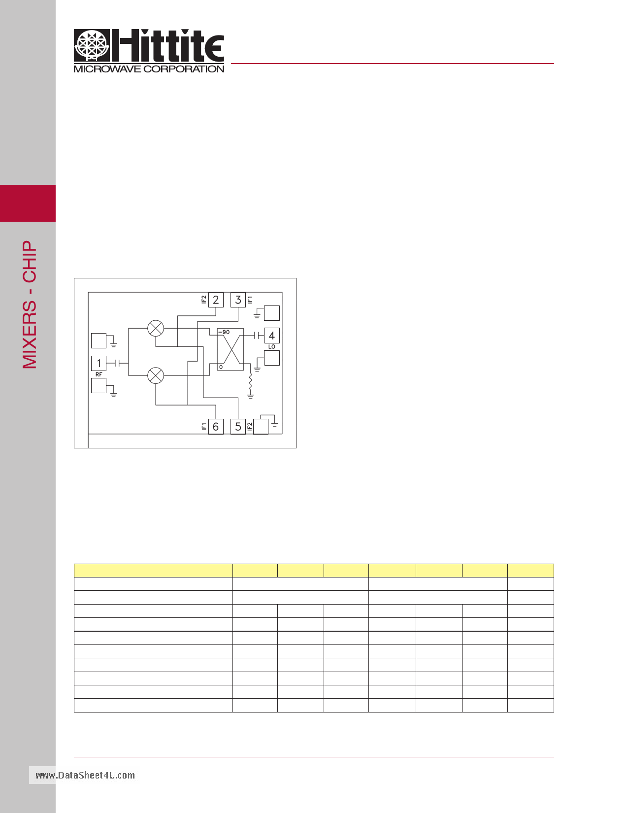
Functional Diagram
HMC521
www.DataSheet4U.com
GaAs MMIC I/Q MIXER
8.5 - 13.5 GHz
Features
Wide IF Bandwidth: DC - 3.5 GHz
Image Rejection: 40 dB
LO to RF Isolation: 45 dB
High Input IP3: +24 dBm
General Description
The HMC521 is a compact I /Q MMIC mixer which can
be used as either an Image Reject Mixer or a Single
Sideband Upconverter. The chip utilizes two standard
Hittite double balanced mixer cells and a 90 degree
hybrid fabricated in a GaAs MESFET process. All
data shown below is taken with the chip mounted in
a 50 Ohm test fixture and includes the effects of 1 mil
diameter x 20 mil length bond wires on each port. A
low frequency quadrature hybrid was used to produce
a 100 MHz USB IF output. This product is a much
smaller alternative to hybrid style Image Reject Mixers
and Single Sideband Upconverter assemblies.
Electrical Specifications, TA = +25° C, IF= 100 MHz, LO = +15 dBm*
Parameter
Min.
Typ.
Frequency Range, RF/LO
8.5 - 13.5
Frequency Range, IF
DC - 3.5
Conversion Loss (As IRM)
8
Image Rejection
20 30
1 dB Compression (Input)
+14
LO to RF Isolation
35 45
LO to IF Isolation
17 22
IP3 (Input)
+23
Amplitude Balance
0.3
Phase Balance
4
* Unless otherwise noted, all measurements performed as downconverter.
Max.
10
Min. Typ.
10.5 - 11.7
DC - 3.5
7.5
30 40
+15
40 50
18 23
+24
0.1
4
Max.
9.5
Units
GHz
GHz
dB
dB
dBm
dB
dB
dBm
dB
Deg
3 - 126
For price, delivery, and to place orders, please contact Hittite Microwave Corporation:
20 Alpha Road, Chelmsford, MA 01824 Phone: 978-250-3343 Fax: 978-250-3373
Order On-line at www.hittite.com
1 page 
v00.1104
HMC521
www.DataSheet4U.com
GaAs MMIC I/Q MIXER
8.5 - 13.5 GHz
3
Pad Descriptions
Pad Number
Function
1 RF
4 LO
2 (5)
IF2
3 (6)
IF1
GND
Description
This pad is AC coupled and matched to
50 Ohms from 8.5 to 13.5 GHz.
This pad is AC coupled and matched to
50 Ohms from 8.5 to 13.5 GHz.
This pad is DC coupled. For applications not requir-
ing operation to DC, this port should be DC blocked
externally using a series capacitor whose value has
been chosen to pass the necessary IF frequency
range. For operation to DC, this pad must not source/
sink more than 3mA of current or die non-function
and possible die failure will result. Pads 5 and 6 are
alternate IF ports.
The backside of the die must be connected
to RF/DC ground.
Interface Schematic
Assembly Diagrams
3 - 130
For price, delivery, and to place orders, please contact Hittite Microwave Corporation:
20 Alpha Road, Chelmsford, MA 01824 Phone: 978-250-3343 Fax: 978-250-3373
Order On-line at www.hittite.com
5 Page | ||
| Páginas | Total 6 Páginas | |
| PDF Descargar | [ Datasheet HMC521.PDF ] | |
Hoja de datos destacado
| Número de pieza | Descripción | Fabricantes |
| HMC520 | GaAs MMIC I/Q MIXER 6 - 10 GHz | Hittite Microwave |
| HMC520A | MMIC I/Q Mixer | Analog Devices |
| HMC520LC4 | GaAs MMIC I/Q MIXER 6 - 10 GHz | Hittite Microwave |
| HMC521 | GaAs MMIC I/Q MIXER 8.5 - 13.5 GHz | Hittite Microwave |
| Número de pieza | Descripción | Fabricantes |
| SLA6805M | High Voltage 3 phase Motor Driver IC. |
Sanken |
| SDC1742 | 12- and 14-Bit Hybrid Synchro / Resolver-to-Digital Converters. |
Analog Devices |
|
DataSheet.es es una pagina web que funciona como un repositorio de manuales o hoja de datos de muchos de los productos más populares, |
| DataSheet.es | 2020 | Privacy Policy | Contacto | Buscar |