|
|
|
PDF HMC904LC5 Data sheet ( Hoja de datos )
| Número de pieza | HMC904LC5 | |
| Descripción | GaAs MMIC I/Q Downconverter | |
| Fabricantes | Hittite Microwave | |
| Logotipo | ||
Hay una vista previa y un enlace de descarga de HMC904LC5 (archivo pdf) en la parte inferior de esta página. Total 12 Páginas | ||
|
No Preview Available !
v00.0310
HMC904LC5www.DataSheet4U.com
GaAs MMIC I/Q DOWNCONVERTER
17 - 24 GHz
9
9-1
Typical Applications
The HMC904LC5 is ideal for:
• Point-to-Point and Point-to-Multi-Point Radio
• Military Radar, EW & ELINT
• Satellite Communications
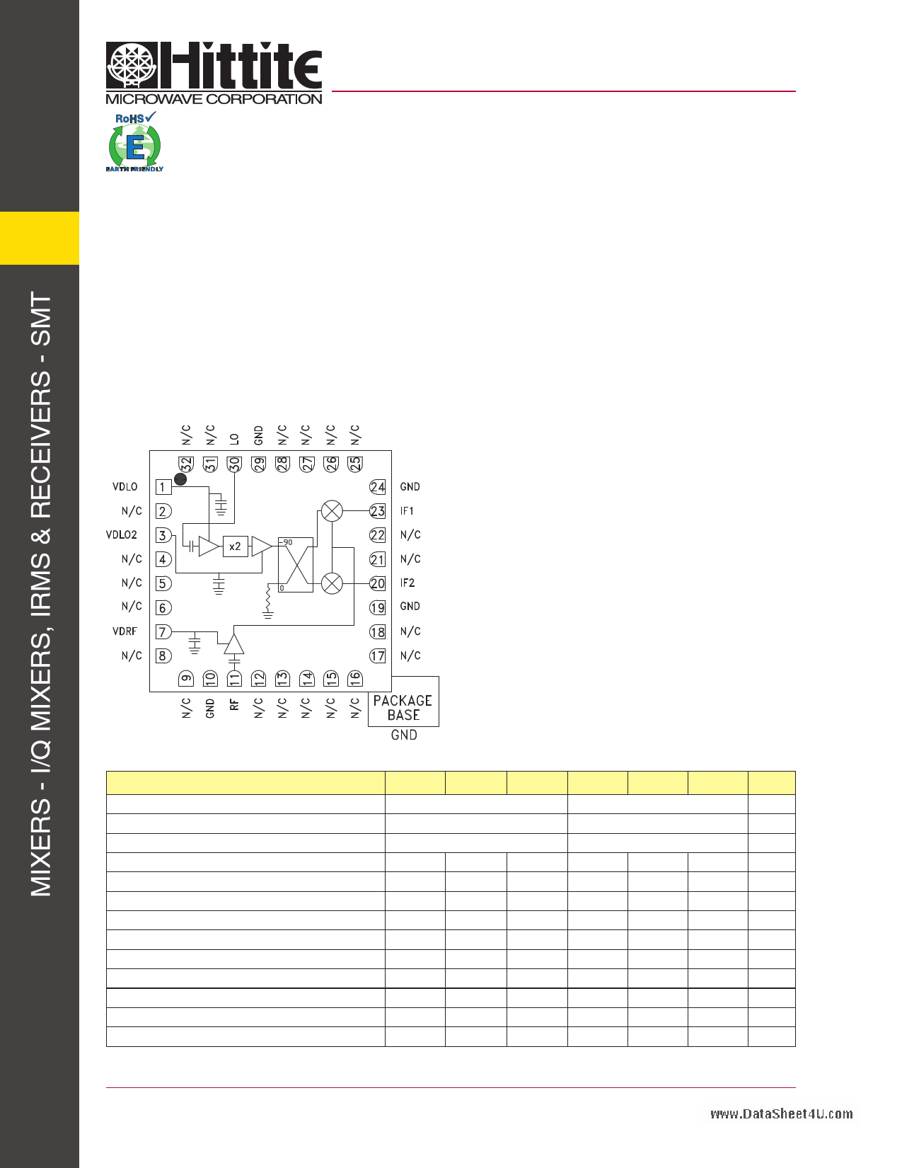
Functional Diagram
Features
Conversion Gain: 12 dB
Image Rejection: 30 dB
2 LO to RF Isolation: 45 dB
Noise Figure: 3 dB
Input IP3: 0 dBm
32 Lead 5x5mm SMT Package: 25mm²
General Description
The HMC904LC5 is a compact GaAs MMIC I/Q
downconverter in a leadless RoHS compliant
SMT package. This device provides a small signal
conversion gain of 12 dB with a noise figure of 3 dB
and 30 dB of image rejection across the frequency
band. The HMC904LC5 utilizes an LNA followed by
an image reject mixer which is driven by an active x2
multiplier. The image reject mixer eliminates the need
for a filter following the LNA, and removes thermal
noise at the image frequency. I and Q mixer outputs
are provided and an external 90° hybrid is needed to
select the required sideband. The HMC904LC5 is a
much smaller alternative to hybrid style image reject
mixer downconverter assemblies, and is compatible
with surface mount manufacturing techniques.
Electrical Specifications, TA = +25 °C, IF = 1000 MHz, LO = +4 dBm, Vdd = 3.5 Vdc USB [1]
Parameter
Frequency Range, RF
Frequency Range, LO
Frequency Range, IF
Conversion Gain (As IRM)
Noise Figure
Image Rejection
1 dB Compression (Input)
2 LO to RF Isolation
2 LO to IF Isolation
IP3 (Input)
Amplitude Balance [2]
Phase Balance [2]
Total Supply Current
[1] Data taken as IRM with external IF 90° Hybrid
[2] Data taken without external 90° hybrid, IF = 500 MHz
Min.
9
25
40
10
Typ.
17 - 20
7.5 - 11.75
DC - 3.5
12
3
35
-8
45
15
0
0.25
7
160
Max.
190
Min. Typ. Max.
20 - 24
8.25 - 12.3
DC - 3.5
9 12
3
15 30
-6
32 40
15 20
0
0.25
7
160 190
Units
GHz
GHz
GHz
dB
dB
dB
dBm
dB
dB
dBm
dB
deg
mA
For price, delivery and to place orders: Hittite Microwave Corporation, 20 Alpha Road, Chelmsford, MA 01824
Phone: 978-250-3343 Fax: 978-250-3373 Order On-line at www.hittite.com
Application Support: Phone: 978-250-3343 or [email protected]
1 page 
v00.0310
HMC904LC5www.DataSheet4U.com
GaAs MMIC I/Q DOWNCONVERTER
17 - 24 GHz
Data Taken as IRM With External IF 90° Hybrid, IF = 1000 MHz
9 Conversion Gain, LSB vs. Temperature
25
Conversion Gain, LSB vs. LO Drive
25
20
+25 C
+85 C
-40 C
15
+2 dBm
20
+4 dBm
+6 dBm
+8 dBm
15
10 10
55
0
16 17 18 19 20 21 22 23 24 25
RF FREQUENCY (GHz)
0
17 18 19 20 21 22 23 24
RF FREQUENCY (GHz)
Image Rejection vs. Temperature
0
-10
+25 C
+85 C
-40 C
-20
-30
-40
-50
-60
16 17 18 19 20 21 22 23 24 25
RF FREQUENCY (GHz)
Input P1dB, LSB vs. Temperature
0
-2 +25 C
+85 C
-4 -40 C
-6
-8
-10
-12
-14
-16
16 17 18 19 20 21 22 23 24
RF FREQUENCY (GHz)
25
9-5
Input IP3, LSB vs. Temperature
15
+25 C
10 +85 C
-40 C
5
0
-5
-10
-15
16 17 18 19 20 21 22 23 24 25
RF FREQUENCY (GHz)
Input IP3, LSB vs. LO Drive
15
+2 dBm
10
+4 dBm
+6 dBm
+8 dBm
5
0
-5
-10
-15
16 17 18 19 20 21 22 23 24 25
RF FREQUENCY (GHz)
* Conversion gain data taken with external IF 90° IF hybrid, LO frequency fixed at 8.5 GHz and RF varied
For price, delivery and to place orders: Hittite Microwave Corporation, 20 Alpha Road, Chelmsford, MA 01824
Phone: 978-250-3343 Fax: 978-250-3373 Order On-line at www.hittite.com
Application Support: Phone: 978-250-3343 or [email protected]
5 Page 
v00.0310
HMC904LC5www.DataSheet4U.com
GaAs MMIC I/Q DOWNCONVERTER
17 - 24 GHz
9
Pin Descriptions
Pin Number
Function
Description
1 VDLO Power supply for first stage of LO amplifier.
2, 4 - 6, 8, 9,
12 - 18, 21, 22,
25 - 28, 31, 32
N/C
The pins are not connected internally; however, all data
shown herein was measured with these pins connected
to RF/DC ground externally.
3
VDLO2
Power supply for second stage of LO amplifier.
7
10, 19, 24, 29
11
20
23
30
VDRF
GND
RF
IF2
IF1
LO
Power supply for RF LNA.
These pins and the exposed ground
paddle must be connected to RF/DC ground.
This pin is AC coupled
and matched to 50 Ohms
This pin is DC coupled. For applications not requir-
ing operation to DC this port should be DC blocked
externally using a series capacitor whose value has
been chosen to pass the necessary frequency range.
For operation to DC, this pin must not sink / source more
than 3 mA of current or part non-function and possible
failure will result.
This pin is AC coupled
and matched to 50 Ohms.
Typical Application Circuit
Interface Schematic
9 - 11
For price, delivery and to place orders: Hittite Microwave Corporation, 20 Alpha Road, Chelmsford, MA 01824
Phone: 978-250-3343 Fax: 978-250-3373 Order On-line at www.hittite.com
Application Support: Phone: 978-250-3343 or [email protected]
11 Page | ||
| Páginas | Total 12 Páginas | |
| PDF Descargar | [ Datasheet HMC904LC5.PDF ] | |
Hoja de datos destacado
| Número de pieza | Descripción | Fabricantes |
| HMC904LC5 | GaAs MMIC I/Q Downconverter | Hittite Microwave |
| Número de pieza | Descripción | Fabricantes |
| SLA6805M | High Voltage 3 phase Motor Driver IC. |
Sanken |
| SDC1742 | 12- and 14-Bit Hybrid Synchro / Resolver-to-Digital Converters. |
Analog Devices |
|
DataSheet.es es una pagina web que funciona como un repositorio de manuales o hoja de datos de muchos de los productos más populares, |
| DataSheet.es | 2020 | Privacy Policy | Contacto | Buscar |