|
|
|
PDF HL1606 Data sheet ( Hoja de datos )
| Número de pieza | HL1606 | |
| Descripción | LED driver IC | |
| Fabricantes | ETC | |
| Logotipo | ||
Hay una vista previa y un enlace de descarga de HL1606 (archivo pdf) en la parte inferior de esta página. Total 6 Páginas | ||
|
No Preview Available !
HL1606
www.DataSheet4U.com
DESCRIPTION
HL1606 is a LED driver IC with SPI controlled. We can get “complex mode changes” by fewer data.
FEATURES
NMOS output
SPI controlled,plus synchronization speed control port: S-I
PWM output,frequency:500Hz
With a internal “change model” unit,only data calls, reducing the amount of data.
Speed control bit,can speed up “changes in a pixel” rate of 2 times.
Latch enable bit,concatenated string at a point can be read or not read data.
Built-6 road, drive two pixels(three-output get a pixel)
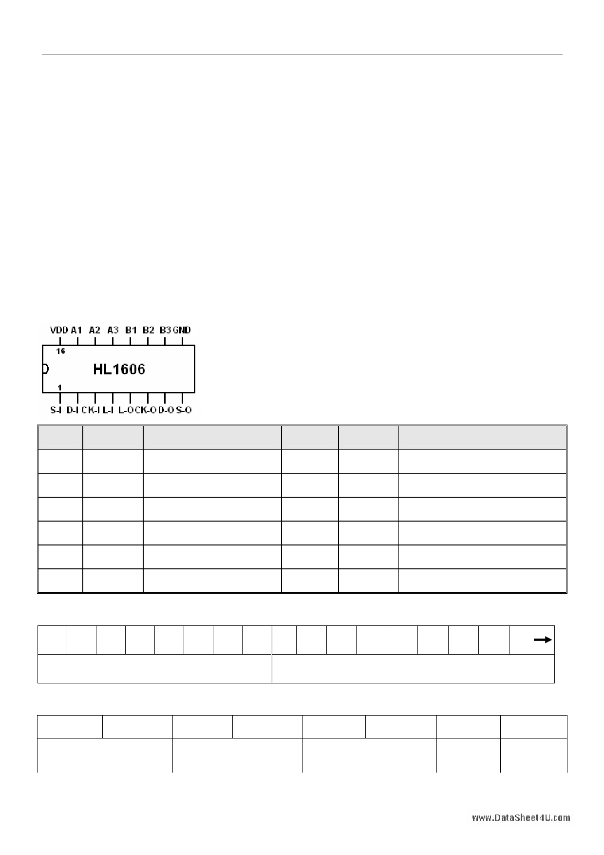
Pin definition
No. Name
Description
No. Name
Description
1
S-I Sync / speed clock input
7
D-O
Data buffer output
2 D-I
Data input
8 S-O Sync / speed clock buffer output
3 CK-I
Clock input
9 GND
GND
4 L-I
Latch signal input
10~12 B3~B1
3 way drive output
5 L-O Latch signal buffer output 13~15 A3~A1
3 way drive output
6 CK-O
Clock buffer output
16 VDD
VDD
Data format
D1 D2 D3 D4 D5 D6 D7 D8 D9 D10 D11 D12 D13 D14 D15 D16 HIGH
A1~A3 LED Control data-1
B1~B3 LED Control date-2
Data format of A1-A3 LED Control data-1(B1-B3 LED Control data-2 can refer it)
D1(D9) D2(D10)
A1(B1)Control bit
D3(D11) D4(D12)
A2(B2)Control bit
D5(D13) D6(D14)
A3(B3)Control bit
D7(D15) D8(D16)
Control bit
Latch
of speed enable bit
Page 1 / 6
1 page 
www.DataSheet4U.com
then input ”0” to the end is okay(red to yellow gradually). Clock signal has been sent to CK_I, sent a “1” to L_I
after 8 clock signal. Change once the signal of S_I, the output series change once. A clock cycle in S_I,.
output is keep in 512Hz refresh frequency, to maintain the same level(series) of output duty cycle refresh. If
no data sent to S_I, output will remain the same duty cycle refresh. Just finished in a color change, change
the data of D-I.
Application
+5V
OUT1
OUT2
OUT3
OUT4
OUT5
OUT6
VCC
78L0 5
OUT
OUT
MOSFET N
(1)
U1
S_I
D_I
CK_I
L_I
104
※
VDD
S_O
D_O
CK_O
L_O
B3
B2
B1
A3
A2
GND A1
47uF
104
※
VDD
U2
S_O
D_O
CK_O
L_O
B3
B2
B1
A3
A2
GND A1
(2) (3)
+5V
47uF
104
※
VDD
U3
S_O
D_O
CK_O
L_O
B3
B2
B1
A3
A2
GND A1
47uF
→
UN
VDD
104
※
S_O
D_O
CK_O
L_O
B3
B2
B1
A3
A2
GND A1
R#
47uF
(4)
Application Notes
1. Picture(1),1st connection method: triode will not connect to output of IC, output current reach 30Ma,output
can connect to two-ways, ensure that the output voltage must be less than 6V.
2. Picture(2), 2nd connection method: triode connect to output of IC. Because the NPN-type transistor at the
base took on the extreme pull-up resistor, the “output duty cycle of IC” and the” LED brightness” is
inversely proportional to. When the IC doesn’t output, the transistor fully conducting, LED full-bright.
Page 5 / 6
5 Page | ||
| Páginas | Total 6 Páginas | |
| PDF Descargar | [ Datasheet HL1606.PDF ] | |
Hoja de datos destacado
| Número de pieza | Descripción | Fabricantes |
| HL1606 | LED driver IC | ETC |
| Número de pieza | Descripción | Fabricantes |
| SLA6805M | High Voltage 3 phase Motor Driver IC. |
Sanken |
| SDC1742 | 12- and 14-Bit Hybrid Synchro / Resolver-to-Digital Converters. |
Analog Devices |
|
DataSheet.es es una pagina web que funciona como un repositorio de manuales o hoja de datos de muchos de los productos más populares, |
| DataSheet.es | 2020 | Privacy Policy | Contacto | Buscar |