|
|
|
PDF NUF8610MN Data sheet ( Hoja de datos )
| Número de pieza | NUF8610MN | |
| Descripción | 8-Channel EMI Filter | |
| Fabricantes | ON Semiconductor | |
| Logotipo | ||
Hay una vista previa y un enlace de descarga de NUF8610MN (archivo pdf) en la parte inferior de esta página. Total 6 Páginas | ||
|
No Preview Available !
NUF8610MN
8-Channel EMI Filter with
Integrated ESD Protection
The NUF8610MN is a eight−channel (C−R−C) Pi−style EMI filter
array with integrated ESD protection. Its typical component values of
R = 50 W and C = 8.5 pF deliver a cutoff frequency of 260 MHz and
stop band attenuation greater than −15 dB from 800 MHz to 2.2 GHz.
This performance makes the part ideal for parallel interfaces with
data rates up to 173 Mbps in applications where wireless interference
must be minimized. The specified attenuation range is very effective
in minimizing interference from 2G/3G, GPS, Bluetooth® and
WLAN signals.
The NUF8610MN is available in the low−profile 16−lead 1.6 mm x
4.0 mm DFN16 surface mount package.
Features/Benefits
• ±8.0 kV ESD Protection on each channel (IEC61000−4−2 Level 4,
Contact Discharge)
• R/C Values of 50 W and 8.5 pF deliver Exceptional S21 Performance
Characteristics of 260 MHz f3dB and −15 dB Stop Band Attenuation
from 800 MHz to 2.2 GHz
• Integrated EMI/ESD System Solution in DFN Package Offers
Exceptional Cost, System Reliability and Space Savings
• This is a Pb−Free Device
Applications
• EMI Filtering for LCD and Camera Data Lines
• EMI Filtering and Protection for I/O Ports and Keypads
http://onsemi.com
MARKING
DIAGRAM
1
16 DFN
CASE 506AC
1
846
AYW
G
846 = Specific Device Code
A = Assembly Location
Y = Year
W = Work Week
G = Pb−Free Package
ORDERING INFORMATION
Device
Package
Shipping†
NUF8610MNTXG DFN16 4000 / Tape & Reel
(Pb−Free)
†For information on tape and reel specifications,
including part orientation and tape sizes, please
refer to our Tape and Reel Packaging Specifications
Brochure, BRD8011/D.
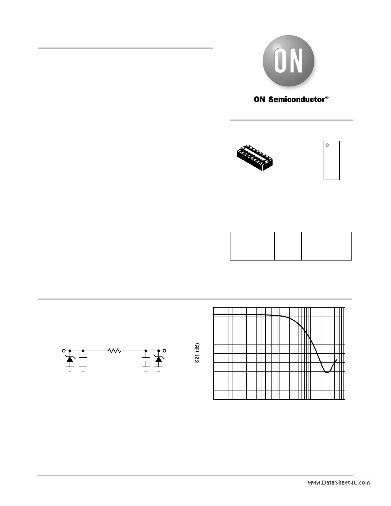
Filter + ESDn
R = 50 W
Cd = 8.5 pF Cd = 8.5 pF
Filter + ESDn
See Table 1 for pin description
www.DataSheet4U.com
Figure 1. Electrical Schematic
0
−5
−10
−15
−20
−25
−30
−35
−40
−45
−50
1.E+06
1.E+07
1.E+08
1.E+09
FREQUENCY (Hz)
1.E+10
Figure 2. Insertion Loss Characteristic
(S21 Measurement)
© Semiconductor Components Industries, LLC, 2009
August, 2009 − Rev. 1
1
Publication Order Number:
NUF8610MN/D
1 page 
NUF8610MN
Table 2. Frequency Chart
Bandwidth
Maximum Supported
Frequency
3 dB –
100 MHz
33.33 MHz (f1)
6 dB –
200 MHz
66.67 MHz (f2)
9 dB –
300 MHz
100 MHz (f3)
Third Harmonic
Frequency
100 MHz
200 MHz
300 MHz
Considering that 85% of the amplitude of the square is in
the first two terms of the Fourier series approximation most
of the signal content is at the fundamental (maximum
supported) frequency and the third harmonic frequency. If a
signal with a frequency of 33.33 MHz is input to this filter,
the first two terms are sufficiently passed such that the signal
is only mildly affected, as is shown in Figure 10a. If a signal
with a frequency of 66.67 MHz is input to this same filter,
the third harmonic term is significantly attenuated. This
serves to round the signal edges and skew the waveform, as
is shown in Figure 10b. In the case that a 100 MHz signal is
input to this filter, the third harmonic term is attenuated even
further and results in even more rounding of the signal edges
as is shown in Figure 10c. The result is the degradation of the
data being transmitted making the digital data (1’s and 0’s)
more difficult to discern. This does not include effects of
other components such as interconnect and other path losses
which could further serve to degrade the signal integrity.
While some filter products may specify the 6 dB or 9 dB
bandwidths, actually using these to calculate supported
frequencies (and corresponding data rates) results in
significant signal degradation. To ensure the best signal
integrity possible, it is best to use the 3 dB bandwidth to
calculate the achievable data rate.
Input Waveform
a) Frequency = f1
Output Waveform
Input Waveform
b) Frequency = f2
Output Waveform
www.DataSheet4U.com
Input Waveform
c) Frequency = f3
Output Waveform
Figure 10. Input and Output Waveforms of Filter
http://onsemi.com
5
5 Page | ||
| Páginas | Total 6 Páginas | |
| PDF Descargar | [ Datasheet NUF8610MN.PDF ] | |
Hoja de datos destacado
| Número de pieza | Descripción | Fabricantes |
| NUF8610MN | 8-Channel EMI Filter | ON Semiconductor |
| Número de pieza | Descripción | Fabricantes |
| SLA6805M | High Voltage 3 phase Motor Driver IC. |
Sanken |
| SDC1742 | 12- and 14-Bit Hybrid Synchro / Resolver-to-Digital Converters. |
Analog Devices |
|
DataSheet.es es una pagina web que funciona como un repositorio de manuales o hoja de datos de muchos de los productos más populares, |
| DataSheet.es | 2020 | Privacy Policy | Contacto | Buscar |