|
|
|
PDF HMC987LP5E Data sheet ( Hoja de datos )
| Número de pieza | HMC987LP5E | |
| Descripción | LOW NOISE 1:9 FANOUT BUFFER | |
| Fabricantes | Hittite Microwave Corporation | |
| Logotipo | ||
Hay una vista previa y un enlace de descarga de HMC987LP5E (archivo pdf) en la parte inferior de esta página. Total 24 Páginas | ||
|
No Preview Available !
www.DataSheet.co.kr
3
v00.0611
Typical Applications
The HMC987LP5E is suitable for:
• SONET, Fibre Channel, GigE Clock Distribution
• ADC/DAC Clock Distribution
• Low Skew and Jitter Clock or Data Fanout
• Wireless/Wired Communications
• Level Translation
• High Performance Instrumentation
• Medical Imaging
• Single-Ended to Differential Conversion
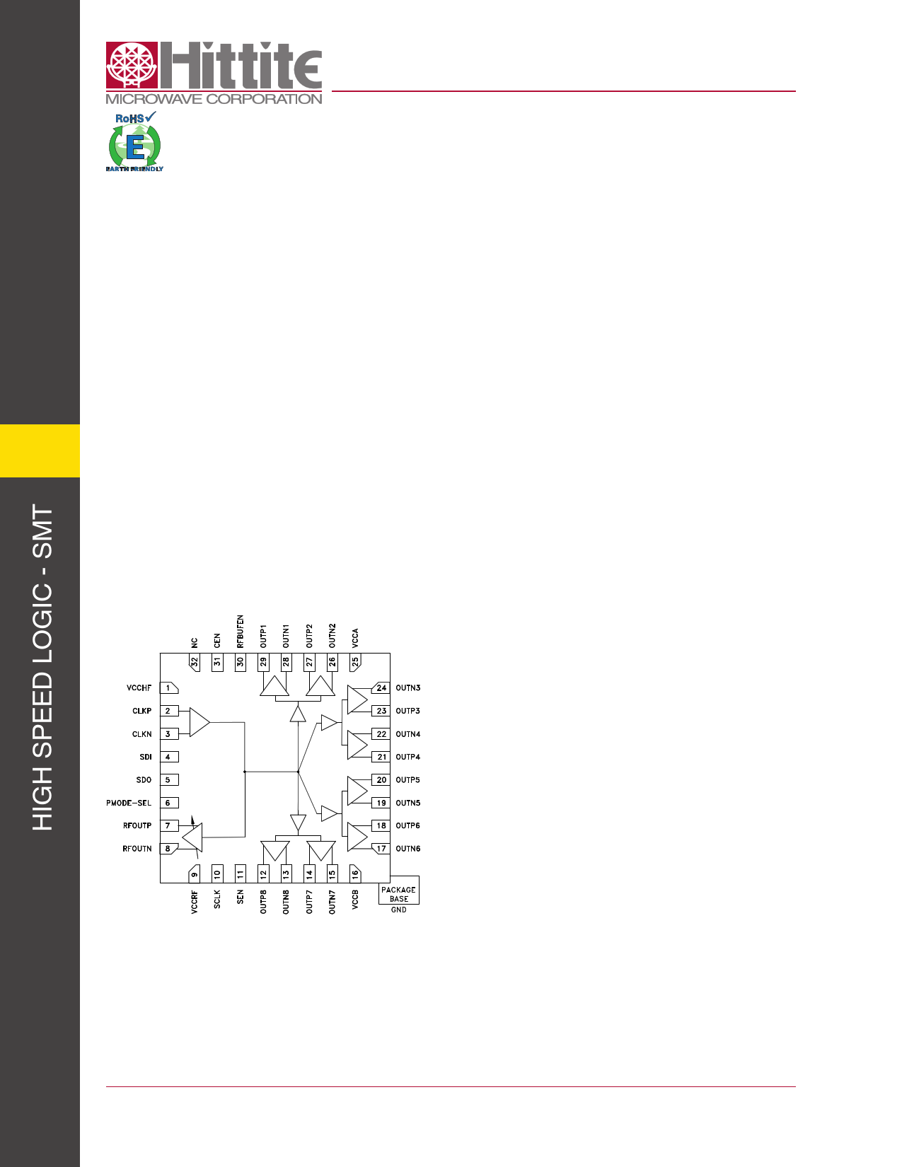
Functional Diagram
HMC987LP5E
LOW NOISE 1:9 FANOUT BUFFER
DC - 8 GHz
Features
Ultra Low Noise Floor: -166 dBc/Hz @ 2 GHz
Wideband: DC - 8 GHz Operating Frequency
Flexible Input Interface:
LVPECL, LVDS, CML, CMOS Compatible
AC or DC Coupling
On-Chip Termination 50 or 150 Ω (100/300 Ω Diff.)
Multiple Output Drivers:
Up to 8 Differential or 16 Single-Ended LVPECL
Outputs:
800 mVpp into 50 Ω Single-Ended (+3 dBm Fo)
One Adjustable Power CML/RF Output:
-9 to 3 dBm Single-Ended
Serial or Parallel Control, Hardware Chip-Enable
Power-Down Current < 1 uA
32 Lead 5x5 mm SMT Package 25 mm2
General Description
The HMC987LP5E 1-to-9 fanout buffer is designed
for low noise clock distribution. It is intended to
generate relatively square wave outputs with rise/
fall times < 100 ps. The low skew and jitter outputs
of the HMC987LP5E, combined with its fast rise/
fall times, leads to controllable low-noise switching
of downstream circuits such as mixers, ADCs/DACs
or SERDES devices. The noise floor is particularly
important in these applications, when the clock-
network bandwidth is wide enough to allow square-
wave switching. Driven at 2 GHz, outputs of the
HMC987LP5E have a noise floor of -166 dBc/Hz,
corresponding to a jitter density of 0.6 asec/rtHz - or
50 fs over an 8 GHz bandwidth.
The input stage can be driven single-ended or
differentially, in a variety of signal formats (CML,
LVDS, LVPECL or CMOS), AC or DC coupled. The
input stage also features adjustable input impedance.
It has 8 LVPECL outputs, and 1 CML output with
adjustable swing/power-level in 3 dB steps.
Individual output stages may be enabled or disabled
for power-savings when not required using either
hardware control pins, or under control of a serial-port
interface.
3-1
For price, delivery and to place orders: Hittite Microwave Corporation, 2 Elizabeth Drive, Chelmsford, MA 01824
978-250-3343 tel • 978-250-3373 fax • Order On-line at www.hittite.com
Application Support: [email protected]
Datasheet pdf - http://www.DataSheet4U.net/
1 page 
www.DataSheet.co.kr
v00.0611
HMC987LP5E
LOW NOISE 1:9 FANOUT BUFFER
DC - 8 GHz
TYPICAL PERFORMANCE CHARACTERISTICS
Unless otherwise specified: T = 27 °C, Regulated VDD = 3.3 V, 2 GHz, 6 dBm in, AC coupled single ended input and output, 120 Ω/leg DC termination,
AC coupled into 50 Ω measuring load.
Figure 1. LVPECL Output vs. Frequency [1]
0.4
4 GHz OUTP 4 GHz OUTN
0.3
2 GHz OUTP
0.2
0.1
Figure 2. LVPECL Output vs. Frequency [1]
0.6
0.4
0.2
00
-0.1
-0.2
-0.3
-0.4
-800
2 GHz OUTN
1 GHz OUTP
1 GHz OUTN
-600 -400 -200
0
200 400 600 800
TIME (picoseconds)
-0.2
-0.4
-0.6
-0.8
0
4 GHz
2 GHz
1 GHz
20 40 60 80 100 120
TIME (ps)
Figure 3. Current Consumption vs. Num.
of Enabled Buffers & Load Resistors[2]
500
120 Ohm DC Termination
400
200 Ohm DC Termination
300
300 Ohm DC Termination
200
Figure 4. Skew of LVPECL Outputs
Relative to Output Channel 1 [4]
15
10
5
0
-5
100
Ground Current (Does not depend on termination)
0
1 2 3 4 5 5 6 7 8 RF Min RF Max
NUMBER OF OUTPUTS SUCCESSIVELY TURNED ON
Figure 5. Fundamental Output Power vs.
Input Power [3]
5
-10
-15
P1 P2 P3 P4 P5 P6 P7 P8
OUTPUT CHANNEL
Figure 6. Evaluation Board LVPECL Output
Trace Loss vs. Frequency [5]
0
400 MHz
0
2 GHz
-5
3 GHz
-1
-2
-3
4 GHz
-10
-4
5 GHz
-15
6 GHz
-5
-6
-20 -7
-30 -24 -18 -12
-6
0
6
100
1000
10000
INPUT POWER (dBm)
OUTPUT FREQUENCY (MHz)
[1] +2dBm input, Uncorrected for board loss. Measurement is band limited by the trace bandwidth of 7 GHz.
[2] Buffers 1 through 8 are successively turned on. RF Min - RF buffer turned on with minimum gain, RF Max - RF buffer turned on with maximum gain
[3] 200 Ω Termination, Corrected for board loss.
[4] Characterized at 2 GHz, Effects of customer evaluation board skew and loss are embedded.
[5] The graph shows only output trace distortion.
For price, delivery and to place orders: Hittite Microwave Corporation, 2 Elizabeth Drive, Chelmsford, MA 01824
978-250-3343 tel • 978-250-3373 fax • Order On-line at www.hittite.com
Application Support: [email protected]
3
3-5
Datasheet pdf - http://www.DataSheet4U.net/
5 Page 
www.DataSheet.co.kr
Outline Drawing
v00.0611
HMC987LP5E
LOW NOISE 1:9 FANOUT BUFFER
DC - 8 GHz
3
NOTES:
[1] PACKAGE BODY MATERIAL: LOW STRESS INJECTION MOLDED PLASTIC SILICA AND SILICON IMPREGNATED.
[2] LEAD AND GROUND PADDLE MATERIAL: COPPER ALLOY.
[3] LEAD AND GROUND PADDLE PLATING: 100% MATTE TIN.
[4] DIMENSIONS ARE IN INCHES [MILLIMETERS].
[5] LEAD SPACING TOLERANCE IS NON-CUMULATIVE.
[6] PAD BURR LENGTH SHALL BE 0.15 mm MAX. PAD BURR HEIGHT SHALL BE 0.05 mm MAX.
[7] PACKAGE WARP SHALL NOT EXCEED 0.05 mm
[8] ALL GROUND LEADS AND GROUND PADDLE MUST BE SOLDERED TO PCB RF GROUND.
[9] REFER TO HITTITE APPLICATION NOTE FOR SUGGESTED PCB LAND PATTERN.
Table 4. Package Information
Part Number
Package Body Material
Lead Finish
HMC987LP5E RoHS-compliant Low Stress Injection Molded Plastic 100% matte Sn
[1] 4-Digit lot number XXXX
[2] Max peak reflow temperature of 260°C
MSL Rating
MSL1[2]
Package Marking [1]
H987
XXXX
For price, delivery and to place orders: Hittite Microwave Corporation, 2 Elizabeth Drive, Chelmsford, MA 01824
978-250-3343 tel • 978-250-3373 fax • Order On-line at www.hittite.com
Application Support: [email protected]
3 - 11
Datasheet pdf - http://www.DataSheet4U.net/
11 Page | ||
| Páginas | Total 24 Páginas | |
| PDF Descargar | [ Datasheet HMC987LP5E.PDF ] | |
Hoja de datos destacado
| Número de pieza | Descripción | Fabricantes |
| HMC987LP5E | LOW NOISE 1:9 FANOUT BUFFER | Hittite Microwave Corporation |
| Número de pieza | Descripción | Fabricantes |
| SLA6805M | High Voltage 3 phase Motor Driver IC. |
Sanken |
| SDC1742 | 12- and 14-Bit Hybrid Synchro / Resolver-to-Digital Converters. |
Analog Devices |
|
DataSheet.es es una pagina web que funciona como un repositorio de manuales o hoja de datos de muchos de los productos más populares, |
| DataSheet.es | 2020 | Privacy Policy | Contacto | Buscar |