|
|
|
PDF 78M6631 Data sheet ( Hoja de datos )
| Número de pieza | 78M6631 | |
| Descripción | 3-Phase Power-Measurement IC | |
| Fabricantes | Maxim Integrated Products | |
| Logotipo | ||
Hay una vista previa y un enlace de descarga de 78M6631 (archivo pdf) en la parte inferior de esta página. Total 30 Páginas | ||
|
No Preview Available !
www.DataSheet.co.kr
19-6039; Rev 1; 1/12
DS_6631_056
DESCRIPTION
The Teridian™ 78M6631 is a highly integrated 3-phase
power measurement and monitoring system-on-chip
(SoC), with a 10 MHz 8051-compatible MPU core and
Single Converter Technology® containing a 22-bit delta-
sigma converter and 32-bit compute engine (CE). The
78M6631 has been designed specifically for a wide
variety of applications requiring 3-phase power and
quality measurements. It supports both Delta and Wye
configurations.
At the measurement interface, the device provides six
analog inputs including three differential current and three
voltage for interfacing to current and voltage sensors. The
device provides better than 0.5% accuracy over a wide
2000:1 dynamic range.
The integrated MPU core and 128 KB of flash memory
provide a flexible means of configuration, post-
processing, data formatting, interfacing to host processor
via a UART or SPI interface, or using DIO pins for LEDs
or relay control. Complete firmware is available from
Maxim and can be loaded into the IC during
manufacturing test.
78M6631
3-Phase Power-
Measurement IC
DATA SHEET
FEATURES
• < 0.5% Watt Accuracy Over 2000:1 Current
Range and Over Temperature
• Exceeds IEC 62053/ANSI C12.20 Standards
• Voltage Reference < 40 ppm/°C
• Six Analog Inputs Supporting 3-Phase Voltage
and Current Measurement Inputs
• Pin- or Biselectable Delta or Wye Configuration
• 22-Bit Delta-Sigma ADC with Independent 32-
Bit Compute Engine (CE)
• 8-Bit MPU (80515), One Clock Cycle per
Instruction with 4 KB MPU XRAM
• 128 KB Flash with Security
• 32 kHz Time Base with Hardware Watchdog
Timer
• UART, I2C, and High-Speed Slave SPI Host
Interface Options
• 17 General-Purpose 5 V Tolerant I/O Pins
• Packaged in a RoHS-Compliant (6/6)
Lead(Pb)-Free 56-Pin TQFN
• Application Firmware Includes (per Phase):
o True RMS Current and Voltage Calculations
o Active, Reactive, Apparent, Fundamental,
and Harmonic Power Calculations
o Fundamental and Harmonic Current and
Voltage Calculations
o Line Frequency and Power Factor
Calculations
o Phase Compensation (±18° at 60 Hz)
o Built-In Calibration Routines
o Programmable Alarm Thresholds
o Command Line (UART) Communications
o High-Speed SPI Communications
Teridian is a trademark and Single Converter Technology is a registered trademark of Maxim Integrated Products, Inc.
Rev 1
1
Datasheet pdf - http://www.DataSheet4U.net/
1 page 
www.DataSheet.co.kr
DS_6631_056
78M6631 Data Sheet
1 Hardware Functional Description
1.1 Hardware Overview
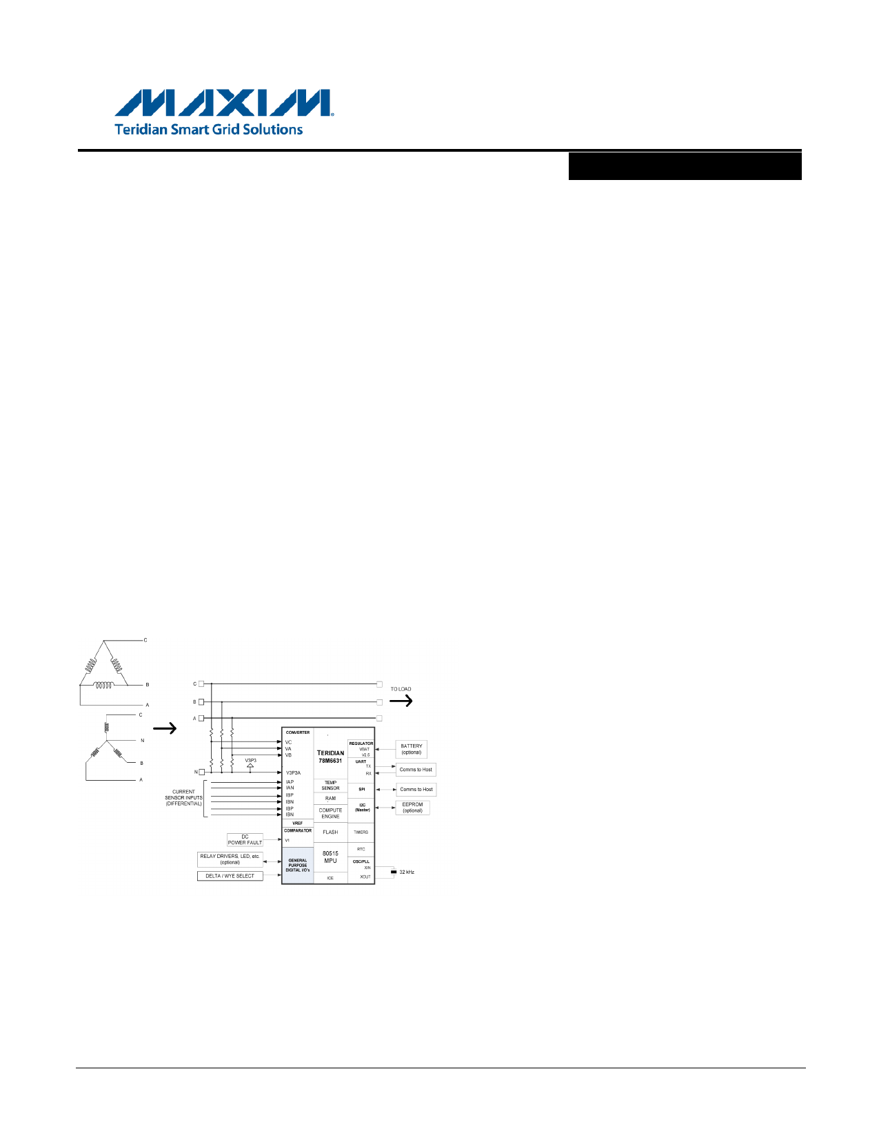
The Teridian 78M6631 single-chip power measurement and monitoring device integrates all the primary
AC measurement and control blocks required to implement the 3-phase power measurement and
monitoring system.
The 78M6631 includes:
• Six input analog front-end (AFE) (3 Differential Current/3 Voltage)
• Independent digital computation engine (CE)
• 8051-compatible microprocessor (MPU) which executes one instruction per clock cycle (80515)
• Precision voltage reference
• Temperature sensor
• RAM and flash memory
• A variety of I/O pins
• Communication Interfaces: UART, SPI, and I2C (Master)
Various current sensor technologies are supported including Current Transformers (CT), Resistive
Shunts, and Rogowski coils.
The 32-bit compute engine (CE) of the 78M6631 sequentially process the samples from the analog inputs
on pins IA, IB, IC, VA, VB, and VC and performs calculations to measure active power (Watts), reactive
power (VARs), apparent power (VAs), power factor, fundamental power, and harmonic power for three
independent phases. RMS, fundamental, and harmonic currents and voltages are also computed for each
phase. Totals are available for most results.
Figure 1 provides a block diagram of the 78M6631 IC. A detailed description of the various functional
blocks follows.
Refer to the applicable Firmware Description Document for additional supported functionality.
Rev 1
5
Datasheet pdf - http://www.DataSheet4U.net/
5 Page 
www.DataSheet.co.kr
DS_6631_056
78M6631 Data Sheet
1.10 Oscillator
The 78M6631 oscillator drives a standard 32.768 kHz quartz crystal. These crystals are accurate and do
not require a high-current oscillator circuit. The 78M6631 oscillator has been designed specifically to
handle these crystals and is compatible with their high impedance and limited power handling capability.
The oscillator is powered directly and only from V3P3D, which therefore must be connected to a DC
voltage source not to exceed 4 V.
Since the oscillator is self-biasing, an external resistor must not be connected across the crystal.
1.11 PLL and Internal Clock Generation
Timing for the device is derived from the 32.768 kHz crystal oscillator output. The PLL and on-chip timing
functions provide several clocks which include:
• The MPU clock (CKMPU)
• The emulator clock (2 x CKMPU)
• The clock for the CE (CKCE)
• The delta-sigma ADC and FIR clock(CKADC, CKFIR)
These internal clocks can be adjusted for various programmable rates which affect device functionality.
Refer to the 78M6631 Programmer’s Reference Manual for more information regarding the
programmability of the 78M6631 PLL and internal clock generation modules.
1.12 Real-Time Clock (RTC)
The RTC circuit is driven directly by the crystal oscillator. The RTC consists of a counter chain and output
registers. The counter chain consists of registers for seconds, minutes, hours, day of week, day of month,
month, and year (including leap years). Refer to the 78M6631 Programmer’s Reference Manual for more
information regarding the use of the 78M6631 RTC.
1.13 Hardware Watchdog Timer
V3P3
V3P3 - 10mV
V3P3 -
400mV
VBIAS
V1
In addition to the basic watchdog timer included in the 80515 MPU, an
independent, robust, fixed-duration, watchdog timer (WDT) is included in
WDT dis- the device. It uses the crystal oscillator as its time base and must be
abled refreshed by the MPU firmware at least every 1.5 seconds. When not
refreshed on time the WDT overflows, and the part is reset as if the RESET
pin were pulled high, except that the IORAM bits are maintained. 4096
Normal oscillator cycles (or 125 ms) after the WDT overflow, the MPU is launched
operation,
WDT
from program address 0x0000. Asserting ICE_E deactivates the WDT.
enabled
The WDT can also be disabled by connecting the V1 pin to V3P3D. This
also deactivates V1 power fault detection. Since there is no method in
firmware to disable the crystal oscillator or the WDT, it is guaranteed that
whatever state the part might find itself in, upon watchdog overflow, the part
Battery
modes
is reset to a known state.
0V
Figure 3: Functions Defined by V1
Rev 1
11
Datasheet pdf - http://www.DataSheet4U.net/
11 Page | ||
| Páginas | Total 30 Páginas | |
| PDF Descargar | [ Datasheet 78M6631.PDF ] | |
Hoja de datos destacado
| Número de pieza | Descripción | Fabricantes |
| 78M6631 | 3-Phase Power-Measurement IC | Maxim Integrated Products |
| Número de pieza | Descripción | Fabricantes |
| SLA6805M | High Voltage 3 phase Motor Driver IC. |
Sanken |
| SDC1742 | 12- and 14-Bit Hybrid Synchro / Resolver-to-Digital Converters. |
Analog Devices |
|
DataSheet.es es una pagina web que funciona como un repositorio de manuales o hoja de datos de muchos de los productos más populares, |
| DataSheet.es | 2020 | Privacy Policy | Contacto | Buscar |