|
|
|
PDF HIP6020ACB Data sheet ( Hoja de datos )
| Número de pieza | HIP6020ACB | |
| Descripción | Advanced Dual PWM and Dual Linear Power Controller | |
| Fabricantes | Intersil Corporation | |
| Logotipo | ||
Hay una vista previa y un enlace de descarga de HIP6020ACB (archivo pdf) en la parte inferior de esta página. Total 16 Páginas | ||
|
No Preview Available !
TM
Data Sheet
HIP6020A
April 1999
File Number 4735
Advanced Dual PWM and Dual Linear
Power Controller
The HIP6020A provides the power control and protection for
four output voltages in high-performance, graphics intensive
microprocessor and computer applications. The IC
integrates two PWM controllers and two linear controllers, as
well as the monitoring and protection functions into a 28-pin
SOIC package. One PWM controller regulates the
microprocessor core voltage with a synchronous-rectified
buck converter. The second PWM controller supplies the
computer system’s AGP 1.5V or 3.3V bus power with a
standard buck converter. The linear controllers regulate
power for the 1.5V GTL bus and the 1.8V power for the
North/South Bridge core voltage and/or cache memory
circuits.
The HIP6020A includes an Intel-compatible, TTL 5-input
digital-to-analog converter (DAC) that adjusts the core PWM
output voltage from 1.3VDC to 2.05VDC in 0.05V steps and
from 2.1VDC to 3.5VDC in 0.1V increments. The precision
reference and voltage-mode control provide ±1% static
regulation. The second PWM controller’s output is user-
selectable, through a TTL-compatible signal applied at the
SELECT pin, for levels of 1.5V (±3%) or fully ON switch. The
linear regulators use external N-Channel MOSFETs or
bipolar NPN pass transistors to provide output voltages of
1.5V ±3% (VOUT3) and 1.8V ±3% (VOUT4).
The HIP6020A monitors all the output voltages. A single
Power Good signal is issued when the core is within 10% of
the DAC setting and all other outputs are above their under-
voltage levels. Additional built-in over-voltage protection for
the core output uses the lower MOSFET to prevent output
voltages above 115% of the DAC setting. The PWM
controllers’ over-current function monitors the output current
by using the voltage drop across the upper MOSFET’s
rDS(ON), eliminating the need for a current sensing resistor.
Ordering Information
TEMP.
PART NUMBER RANGE (oC)
PACKAGE
HIP6020ACB
0 to 70 28 Ld SOIC
PKG.
NO.
M28.3
Features
• Provides 4 Regulated Voltages
- Microprocessor Core, AGP Bus, North/South Bridge
and/or Cache Memory, and GTL Bus Power
• Drives N-Channel MOSFETs
• Linear Regulator Drives Compatible with both MOSFET
and Bipolar Series Pass Transistors
• Simple Single-Loop Control Designs
- Voltage-Mode PWM Control
• Fast PWM Converter Transient Response
- High-Bandwidth Error Amplifiers
- Full 0% to 100% Duty Ratios
• Excellent Output Voltage Regulation
- Core PWM Output: ±1% Over Temperature
- AGP Bus PWM Output: ±3% Over Temperature
(1.5V Setting Only)
- Other Outputs: ±3% Over Temperature
• TTL-Compatible 5 Bit DAC Microprocessor Core Output
Voltage Selection
- Wide Range - 1.3VDC to 3.5VDC
• Power-Good Output Voltage Monitor
• Over-Voltage and Over-Current Fault Monitors
- Switching Regulators Use MOSFET’s rDS(ON) Sensing
• Small Converter Size
- Constant Frequency Operation
- 200kHz Free-Running Oscillator; Programmable From
50kHz to Over 1MHz
- Small External Component Count
Applications
• Motherboard Power Regulation for Computers
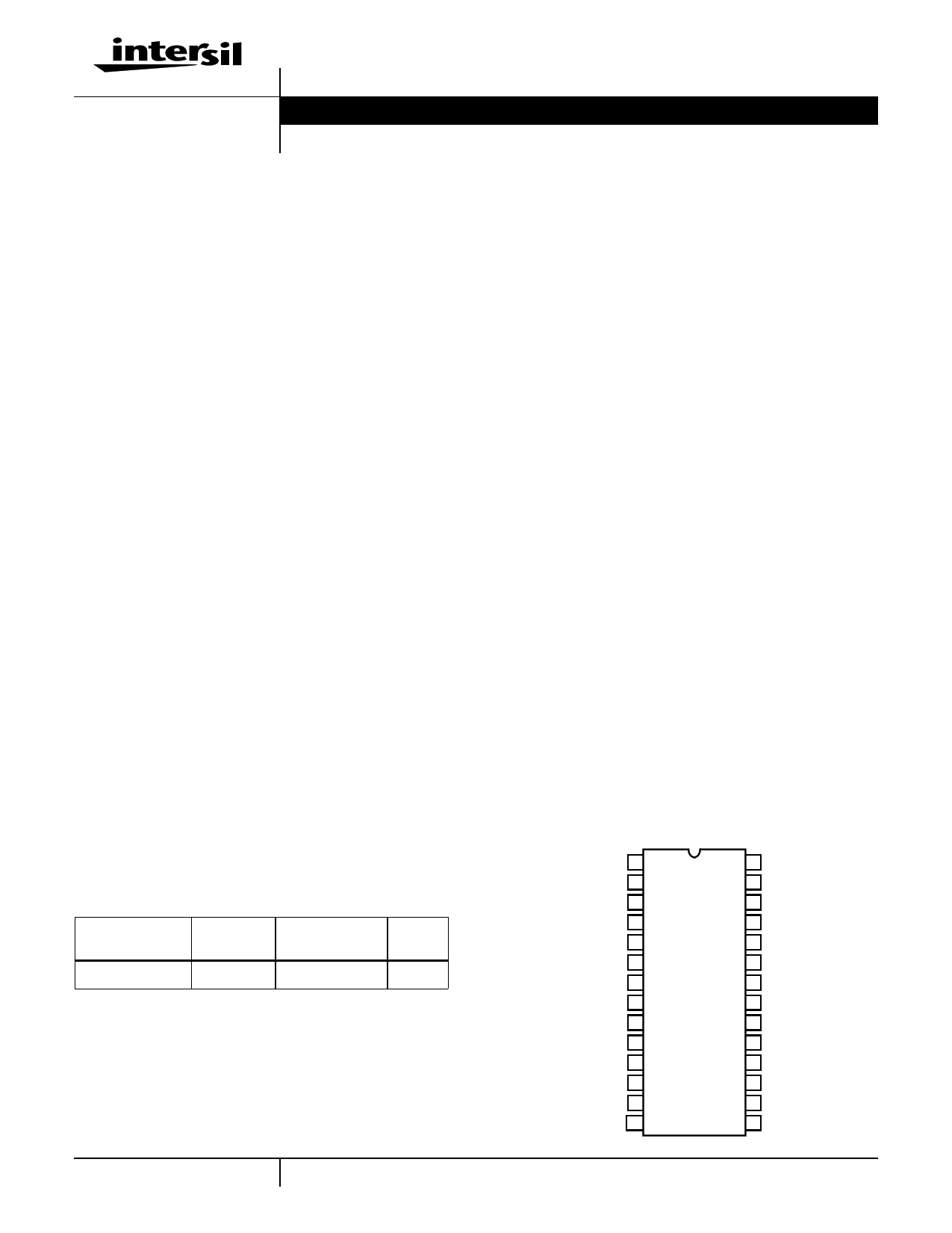
Pinout
HIP6020A (SOIC)
TOP VIEW
UGATE2 1
PHASE2 2
VID4 3
VID3 4
VID2 5
VID1 6
VID0 7
PGOOD 8
OCSET2 9
VSEN2 10
SELECT 11
SS 12
FAULT/RT 13
FB4 14
28 VCC
27 UGATE1
26 PHASE1
25 LGATE1
24 PGND
23 OCSET1
22 VSEN1
21 FB1
20 COMP1
19 FB3
18 DRIVE3
17 GND
16 VAUX
15 DRIVE4
4-1 CAUTION: These devices are sensitive to electrostatic discharge; follow proper IC Handling Procedures.
1-888-INTERSIL or 321-724-7143 | Copyright © Intersil Corporation 1999
1 page 
HIP6020A
Electrical Specifications Recommended Operating Conditions, Unless Otherwise Noted. Refer to Figures 1, 2 and 3 (Continued)
PARAMETER
SYMBOL
TEST CONDITIONS
MIN TYP MAX UNITS
PWM CONTROLLERS GATE DRIVERS
UGATE1,2 Source
UGATE1,2 Sink
LGATE Source
LGATE Sink
PROTECTION
IUGATE
RUGATE
ILGATE
RLGATE
VCC = 12V, VUGATE1 (or VUGATE2) = 6V
VGATE-PHASE = 1V
VCC = 12V, VLGATE1 = 1V
VLGATE = 1V
-1-
- 1.7 3.5
-1-
- 1.4 3.0
A
Ω
A
Ω
VSEN1 Over-Voltage (VSEN1/DACOUT)
VSEN1 Rising
- 115 120
%
FAULT Sourcing Current
OCSET1,2 Current Source
Soft-Start Current
VSEN2 Under-Voltage Threshold
IOVP
IOCSET
ISS
VFAULT/RT = 2.0V
VOCSET = 4.5VDC
SELECT < 0.8V
- 8.5 -
170 200 230
- 28 -
- 75 -
mA
µA
µA
%
SELECT > 2.0V
- 2.475 -
V
VSEN2 Under-Voltage Hysteresis
SELECT < 0.8V
-7-
%
SELECT > 2.0V
- 0.231 -
V
POWER GOOD
VSEN1 Upper Threshold
(VSEN1/DACOUT)
VSEN1 Rising
108 - 110
%
VSEN1 Under-Voltage
(VSEN1/DACOUT)
VSEN1 Rising
92 - 94
%
VSEN1 Hysteresis (VSEN1/DACOUT)
Upper/Lower Threshold
-2-
%
PGOOD Voltage Low
VPGOOD
IPGOOD = -4mA
- - 0.8 V
Typical Performance Curves
1000
100
RT PULLUP
TO +12V
10
RT PULLDOWN TO VSS
10 100
SWITCHING FREQUENCY (kHz)
1000
FIGURE 1. RT RESISTANCE vs FREQUENCY
140
CUGATE1 = CUGATE2 = CLGATE1 = C
120 VIN = 5V ; SELECT < 0.8V
VCC = 12V
100
C = 4800pF
80
C = 3600pF
60
C = 1500pF
40
20 C = 660pF
0
100 200 300 400 500 600 700 800 900 1000
SWITCHING FREQUENCY (kHz)
FIGURE 2. BIAS SUPPLY CURRENT vs FREQUENCY
4-5
5 Page 
HIP6020A
+5VIN
LIN
VOUT2
CIN +12V
COCSET2 CVCC
VCC GND
COCSET1
ROCSET2
Q3
LOUT2
COUT2 CR2
OCSET2 OCSET1
UGATE2
UGATE1
PHASE2
PHASE1
ROCSET1
Q1
LOUT1
VOUT1
LGATE1
SS Q2
COUT1
CR1
VOUT3
CSS
HIP6020A
VOUT4
COUT3
Q4
DRIVE3 DRIVE4
PGND
COUT4
Q5
+3.3VIN
KEY
ISLAND ON POWER PLANE LAYER
ISLAND ON CIRCUIT PLANE LAYER
VIA CONNECTION TO GROUND PLANE
FIGURE 7. PRINTED CIRCUIT BOARD POWER PLANES AND
ISLANDS
PWM1 Controller Feedback Compensation
Both PWM controllers use voltage-mode control for output
regulation. This section highlights the design consideration
for a voltage-mode controller requiring external
compensation. Apply these methods and considerations
only to the synchronous PWM controller. The considerations
for the standard PWM controller are presented separately.
Figure 11 highlights the voltage-mode control loop for a
synchronous-rectified buck converter. The output voltage
(VOUT) is regulated to the Reference voltage level. The
reference voltage level is the DAC output voltage (DACOUT) for
PWM1. The error amplifier output (VE/A) is compared with the
oscillator (OSC) triangular wave to provide a pulse-width
modulated wave with an amplitude of VIN at the PHASE node.
The PWM wave is smoothed by the output filter (LO and CO).
The modulator transfer function is the small-signal transfer
function of VOUT/VE/A. This function is dominated by a DC
Gain, given by VIN/VOSC, and shaped by the output filter, with
a double pole break frequency at FLC and a zero at FESR.
Modulator Break Frequency Equations
FLC=
-------------------1--------------------
2π × LO × CO
FESR= 2----π-----×-----E----S--1---R------×----C-----O---
The compensation network consists of the error amplifier
(internal to the HIP6020A) and the impedance networks ZIN
and ZFB. The goal of the compensation network is to provide a
4-11
∆VOSC
OSC
PWM
COMP
-
+
VIN
DRIVER
LO VOUT
DRIVER
PHASE
CO
VE/A
ZFB
-
+
ERROR
AMP
ZIN
REFERENCE
ESR
(PARASITIC)
DETAILED COMPENSATION COMPONENTS
C2
C1 R2
ZFB VOUT
ZIN
C3 R3
COMP
FB
-
+
HIP6020A
DACOUT
R1
FIGURE 8. VOLTAGE-MODE BUCK CONVERTER
COMPENSATION DESIGN
closed loop transfer function with high 0dB crossing frequency
(f0dB) and adequate phase margin. Phase margin is the
difference between the closed loop phase at f0dB and 180
degrees. The equations below relate the compensation
network’s poles, zeros and gain to the components (R1, R2,
R3, C1, C2, and C3) in Figure 11. Use these guidelines for
locating the poles and zeros of the compensation network:
1. Pick Gain (R2/R1) for desired converter bandwidth
2. Place 1ST Zero Below Filter’s Double Pole (~75% FLC)
3. Place 2ND Zero at Filter’s Double Pole
4. Place 1ST Pole at the ESR Zero
5. Place 2ND Pole at Half the Switching Frequency
6. Check Gain against Error Amplifier’s Open-Loop Gain
7. Estimate Phase Margin - Repeat if Necessary
Compensation Break Frequency Equations
FZ1 = 2----π-----×-----R---1--2-----×----C-----1--
FP1
=
---------------------------1---------------------------
2π
×
R2
×
C-C----11-----+×-----CC-----22--
FZ2 = 2----π-----×-----(--R-----1-----+-1----R-----3---)----×-----C-----3-
FP2 = -2---π-----×-----R---1--3-----×----C-----3--
Figure 12 shows an asymptotic plot of the DC-DC converter’s
gain vs. frequency. The actual Modulator Gain has a high gain
peak dependent on the quality factor (Q) of the output filter,
which is not shown in Figure 12. Using the above guidelines
should yield a Compensation Gain similar to the curve plotted.
The open loop error amplifier gain bounds the compensation
11 Page | ||
| Páginas | Total 16 Páginas | |
| PDF Descargar | [ Datasheet HIP6020ACB.PDF ] | |
Hoja de datos destacado
| Número de pieza | Descripción | Fabricantes |
| HIP6020ACB | Advanced Dual PWM and Dual Linear Power Controller | Intersil Corporation |
| Número de pieza | Descripción | Fabricantes |
| SLA6805M | High Voltage 3 phase Motor Driver IC. |
Sanken |
| SDC1742 | 12- and 14-Bit Hybrid Synchro / Resolver-to-Digital Converters. |
Analog Devices |
|
DataSheet.es es una pagina web que funciona como un repositorio de manuales o hoja de datos de muchos de los productos más populares, |
| DataSheet.es | 2020 | Privacy Policy | Contacto | Buscar |