|
|
|
PDF SCE7755 Data sheet ( Hoja de datos )
| Número de pieza | SCE7755 | |
| Descripción | Energy Metering IC | |
| Fabricantes | SilvanChip | |
| Logotipo | ||
Hay una vista previa y un enlace de descarga de SCE7755 (archivo pdf) en la parte inferior de esta página. Total 14 Páginas | ||
|
No Preview Available !
SCE7755
Energy Metering IC with Pulse Output
SCE7755 FEATURES
High Accuracy, Surpasses 50 Hz/60 Hz IEC 687/1036
Less than 0.1% Error over a Dynamic Range of 500 to 1
The SCE7755 Supplies Average Real Power on the Frequency Outputs F1 and F2
The High-Frequency Output CF Is Intended for Calibration and Supplies Instantaneous Real Power
Pin Compatible with AD7755 with Synchronous CF and F1/F2 Outputs
The Logic Output REVP Can Be Used to Indicate a Potential Miswiring or Negative Power
Direct Drive for Electromechanical Counters and Two Phase Stepper Motors (F1 and F2)
A PGA in the Current Channel Allows the Use of Small Values of Shunt and Burden Resistance
Proprietary ADCs and DSP Provide High Accuracy over Large Variations in Environmental Conditions and Time
On-Chip Power Supply Monitoring
On-Chip Creep Protection (No Load Threshold)
On-Chip Reference 2.5 V 8% (30 ppm/C Typical)
with External Overdrive Capability
Single 5 V Supply, Low Power (15 mW Typical)
Low Cost CMOS Process
SCE7755 GENERAL DESCRIPTION
The SCE7755 is pin compatible with the AD7755. The only difference between the SCE7755 and the AD7755 is that the
SCE7755 features a synchronous CF and F1/F2 outputs under all load conditions.
The SCE7755 is a high accuracy electrical energy measurement IC. The part specifications surpass the accuracy requirements
as quoted in the IEC1036 standard. See Analog Devices’ Application Note AN-559 for a description of an IEC1036 watt-hour
meter reference design based on the AD7755.
The only analog circuitry used in the SCE7755 is in the ADCs and reference circuit. All other signal processing (e.g.,
multiplication and filtering) is carried out in the digital domain. This approach provides superior stability and accuracy over
extremes in environmental conditions and over time.
The SCE7755 supplies average real power information on the low-frequency outputs F1 and F2. These logic outputs may be
used to directly drive an electromechanical counter or interface to an MCU. The CF logic output gives instantaneous real power
information. This output is intended to be used for calibration purposes or for interfacing to an MCU.
The SCE7755 includes a power supply monitoring circuit on the AVDD supply pin. The SCE7755 will remain in a reset condition
until the supply voltage on AVDD reaches 4 V. If the supply falls below 4 V, the SCE7755 will also be reset and no pulses will be
issued on F1, F2, and CF.
Internal phase matching circuitry ensures that the voltage and current channels are phase matched whether the HPF in Channel
1 is on or off. An internal no-load threshold ensures that the SCE7755 does not exhibit any creep when there is no load.
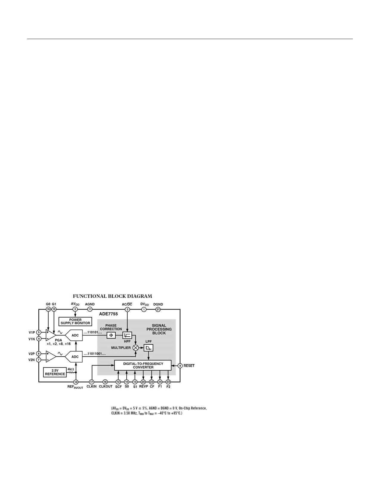
SCE7755 FUNCTIONAL BLOCK DIAGRAM
*U.S. Patents 5,745,323, 5,760,617, 5,862,069, and 5,872,469.
SCE7755 SPECIFICATIONS
Free Datasheet http://www.datasheet4u.com/
1 page 
SCE7755
15, 16 G1, G0
17 CLKIN
18 CLKOUT
20 REVP
21 DGND
22 CF
23, 24 F2, F1
Energy Metering IC with Pulse Output
Selecting
a Frequency for an Energy Meter Application section.
These logic inputs are used to select one of four possible gains for Channel 1, i.e., V1. The
possible
gains are 1, 2, 8, and 16. See Analog Input section.
An external clock can be provided at this logic input. Alternatively, a parallel resonant AT crystal
can
be connected across CLKIN and CLKOUT to provide a clock source for the SCE7755. The
clock
frequency for specified operation is 3.579545 MHz. Crystal load capacitance of between 22 pF
and
33 pF (ceramic) should be used with the gate oscillator circuit.
A crystal can be connected across this pin and CLKIN as described above to provide a clock
source
for the SCE7755. The CLKOUT Pin can drive one CMOS load when an external clock is
supplied at
CLKIN or by the gate oscillator circuit.
This logic output will go logic high when negative power is detected, i.e., when the phase angle
between
the voltage and current signals is greater than 90∞. This output is not latched and will be reset
when
positive power is once again detected. The output will go high or low at the same time as a
pulse is
issued on CF.
This provides the ground reference for the digital circuitry in the SCE7755, i.e., multiplier, filters,
and
digital-to-frequency converter. This pin should be tied to the digital ground plane of the PCB.
The
digital ground plane is the ground reference for all digital circuitry, e.g., counters (mechanical
and
digital), MCUs, and indicator LEDs. For good noise suppression, the analog ground plane
should
only be connected to the digital ground plane at one point only, e.g., a star ground.
Calibration Frequency Logic Output. The CF logic output gives instantaneous real power
informa
tion. This output is intended to be used for calibration purposes. Also see SCF Pin description.
Low Frequency Logic Outputs. F1 and F2 supply average real power information. The logic
outputs
can be used to directly drive electromechanical counters and two phase stepper motors. See
Transfer
Function section.
SCE7755 PHASE ERROR BETWEEN CHANNELS
The HPF (High-Pass Filter) in Channel 1 has a phase lead response. To offset this phase response and equalize the phase
response between channels, a phase correction network is also placed in Channel 1. The phase correction network
matches the phase to within ë 0.1∞ over a range of 45 Hz to 65 Hz and ë 0.2∞ over a range 40 Hz to 1 kHz. See Figures 4
and 5.
SCE7755 POWER SUPPLY REJECTION
This quantifies the SCE7755 measurement error as a percentage of the reading when the power supplies are varied.
For the ac PSR measurement, a reading at nominal supplies (5 V) is taken. A 200 mV rms/100 Hz signal is then introduced
onto the supplies and a second reading obtained under the same input signal levels. Any error introduced is expressed as a
percentage of the reading (see Measurement Error definition).
For the dc PSR measurement, a reading at nominal supplies (5 V) is taken. The supplies are then varied ë 5% and a
second reading is obtained with the same input signal levels. Any error introduced is again expressed as a percentage of
the reading.
SCE7755 ADC OFFSET ERROR
This refers to the dc offset associated with the analog inputs to the ADCs. It means that with the analog inputs connected
Free Datasheet http://www.datasheet4u.com/
5 Page 
SCE7755
Energy Metering IC with Pulse Output
*REVP MUST BE USED IF THE METER IS BIDIRECTIONAL OR DIRECTION OF ENERGY FLOW IS NEEDED
Figure 13. Interfacing the SCE7755 to an MCU
As shown, the frequency output CF is connected to an MCU counter or port. This will count the number of pulses in a given
integration time that is determined by an MCU internal timer. The average power proportional to the average frequency is
given by:
The energy consumed during an integration period is given by:
For the purpose of calibration, this integration time can be 10 to 20 seconds to accumulate enough pulses to ensure correct
averaging of the frequency. In normal operation, the integration time can be reduced to one or two seconds depending, for
example, on the required undate rate of a display. With shorter integration times on the MCU, the amount of energy in each
update may still have some small amount of ripple, even under steady load conditions. However, over a minute or more, the
measured energy will have no ripple.
SCE7755 Power Measurement Considerations
Calculating and displaying power information will always have some associated ripple that will depend on the integration
period used in the MCU to determine average power and also the load. For example, at light loads, the output frequency
may be 10 Hz. With an integration period of two seconds, only about 20 pulses will be counted. The possibility of missing
one pulse always exists, since the SCE7755 output frequency is running asynchronously to the MCU timer. This would
result in a one-in-twenty (or 5%) error in the power measurement.
SCE7755 TRANSFER FUNCTION Frequency Outputs F1 and F2
The SCE7755 calculates the product of two voltage signals (on Channel 1 and Channel 2) and then low-pass filters this
product to extract real power information. This real power information is then converted to a frequency. The frequency
information is output on F1 and F2 in the form of active low pulses. The pulse rate at these outputs is relatively low, e.g.,
0.34 Hz maximum for ac signals with S0 = S1 = 0 (see Table III). This means that the frequency at these outputs is
generated from real power information accumulated over a relatively long period of time. The result is an output frequency
that is proportional to the average real power. The averaging of the real power signal is implicit to the digital-to-frequency
conversion. The output frequency or pulse rate is related to the input voltage signals by the following equation.
where:
Freq = Output frequency on F1 and F2 (Hz)
V1 = Differential rms voltage signal on Channel 1 (Volts)
V2 = Differential rms voltage signal on Channel 2 (Volts)
Gain = 1, 2, 8, or 16, depending on the PGA gain selection made using logic inputs G0 and G1
Free Datasheet http://www.datasheet4u.com/
11 Page | ||
| Páginas | Total 14 Páginas | |
| PDF Descargar | [ Datasheet SCE7755.PDF ] | |
Hoja de datos destacado
| Número de pieza | Descripción | Fabricantes |
| SCE7755 | Energy Metering IC | SilvanChip |
| Número de pieza | Descripción | Fabricantes |
| SLA6805M | High Voltage 3 phase Motor Driver IC. |
Sanken |
| SDC1742 | 12- and 14-Bit Hybrid Synchro / Resolver-to-Digital Converters. |
Analog Devices |
|
DataSheet.es es una pagina web que funciona como un repositorio de manuales o hoja de datos de muchos de los productos más populares, |
| DataSheet.es | 2020 | Privacy Policy | Contacto | Buscar |