|
|
|
PDF AK4388 Data sheet ( Hoja de datos )
| Número de pieza | AK4388 | |
| Descripción | 192kHz 24-Bit 2ch DAC | |
| Fabricantes | AKM | |
| Logotipo | ||
Hay una vista previa y un enlace de descarga de AK4388 (archivo pdf) en la parte inferior de esta página. Total 18 Páginas | ||
|
No Preview Available !
ASAHI KASEI
[AK4388]
AK4388
192kHz 24-Bit 2ch ∆Σ DAC
GENERAL DESCRIPTION
The AK4388 offers the perfect mix for cost and performance based audio systems. Using AKM's multi bit
architecture for its modulator, the AK4388 delivers a wide dynamic range while preserving linearity for
improved THD+N performance. The AK4388 integrates a combination of SCF and CTF filters increasing
performance for systems with excessive clock jitter. The 24 Bit word length and 192kHz sampling rate
make this part ideal for a wide range of applications including DVD-Audio. The AK4388 is offered in a
space saving 16pin TSSOP package.
FEATURES
Sampling Rate Ranging from 8kHz to 192kHz
128 times Oversampling (Normal Speed Mode)
64 times Oversampling (Double Speed Mode)
32 times Oversampling (Quad Speed Mode)
24-Bit 8 times FIR Digital Filter
SCF with High Tolerance to Clock Jitter
Single Ended Output Buffer
Digital de-emphasis
Soft mute
I/F format: 24-Bit MSB justified, 24/16-Bit LSB justified or I2S
Master clock: 256fs, 384fs, 512fs, 768fs or 1152fs (Normal Speed Mode)
256fs or 384fs (Double Speed Mode)
128fs, 192fs (Quad Speed Mode)
THD+N: -90dB
Dynamic Range: 106dB
Power supply: 4.5 to 5.5V
Very Small Package: 16pin TSSOP (6.4mm x 5.0mm)
AK4384 Parallel Mode Compatible
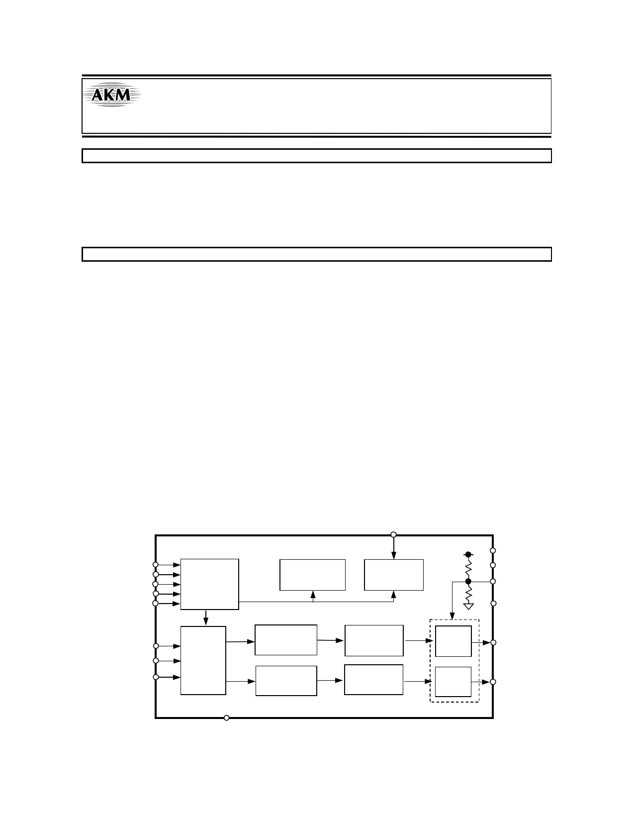
MCLK
DEM
SMUTE
ACKS
DIF0
DIF1
LRCK
BICK
SDTI
Control
Port
De-emphasis
Control
Clock
Divider
Audio
Data
Interface
8X
Interpolator
8X
Interpolator
∆Σ
Modulator
∆Σ
Modulator
SCF
LPF
SCF
LPF
RSTN
MS0485-E-02
-1-
VDD
VSS
VCOM
DZF
AOUTL
AOUTR
2006/08
Free Datasheet http://www.datasheet4u.net/
1 page 
ASAHI KASEI
[AK4388]
FILTER CHARACTERISTICS
(Ta = 25°C; VDD = 4.5 ∼ 5.5V; fs = 44.1kHz)
Parameter
Symbol
min
typ
max Units
Digital filter (DEM = OFF)
Passband
±0.05dB (Note 9)
PB 0
20.0 kHz
–6.0dB
- 22.05 - kHz
Stopband
(Note 9)
SB 24.1
kHz
Passband Ripple
PR
± 0.02
dB
Stopband Attenuation
SA 54
dB
Group Delay
(Note 10)
GD - 19.3 - 1/fs
De-emphasis Filter (DEM = ON)
De-emphasis Error fs = 32kHz
-
-
–1.5/0
dB
(Relative to 0Hz)
fs = 44.1kHz
-
-
–0.2/+0.2
dB
fs = 48kHz
-
-
0/+0.6
dB
Digital Filter + LPF (DEM = OFF)
Frequency Response 20.0kHz fs=44.1kHz
40.0kHz fs=96kHz
80.0kHz fs=192kHz
FR
FR
FR
- ±0.2 -
- ±0.3 -
- +0.1/-0.6 -
dB
dB
dB
Notes: 9. The passband and stopband frequencies scale with fs(system sampling rate).
For example, PB=0.4535×fs (@±0.05dB), SB=0.546×fs.
10. The calculating delay time which occurred by digital filtering. This time is from setting the 16/24bit data
of both channels to input register to the output of analog signal.
MS0485-E-02
-5-
2006/08
Free Datasheet http://www.datasheet4u.net/
5 Page 
ASAHI KASEI
[AK4388]
Zero Detection
When the input data at both channels are continuously zeros for 8192 LRCK cycles, DZF pin goes to “H”. DZF pin
immediately goes to “L” if input data of both channels are not zero after going DZF “H”(Figure 5).
Soft Mute Operation
Soft mute operation is performed at digital domain. When the SMUTE pin goes to “H”, the output signal is attenuated by
-∞ during 1024 LRCK cycles. When the SMUTE pin is returned to “L”, the mute is cancelled and the output attenuation
gradually changes to 0dB during 1024 LRCK cycles. If the soft mute is cancelled within the 1024 LRCK cycles after
starting the operation, the attenuation is discontinued and returned to 0dB by the same cycle. The soft mute is effective for
changing the signal source without stopping the signal transmission.
SMUTE bit
ATT Level
Attenuation
-∞
AOUT
DZF pin
(1)
GD
(2)
(4)
8192/fs
(1)
GD
(3)
Notes:
(1) 1020LRCK cycles (1020/fs) at input data is attenuated to -∞.
(2) The analog output corresponding to the digital input has a group delay, GD.
(3) If the soft mute is cancelled before attenuating to -∞ after starting the operation, the attenuation is discontinued and
returned to ATT level by the same cycle.
(4) When the input data at both channels are continuously zeros for 8192 LRCK cycles, DZF pin goes to “H”. DZF pin
immediately goes to “L” if input data are not zero after going DZF “H”.
Figure 5. Soft Mute and Zero Detection
MS0485-E-02
- 11 -
2006/08
Free Datasheet http://www.datasheet4u.net/
11 Page | ||
| Páginas | Total 18 Páginas | |
| PDF Descargar | [ Datasheet AK4388.PDF ] | |
Hoja de datos destacado
| Número de pieza | Descripción | Fabricantes |
| AK4380 | 100dB 24-BIT 96kHz 2CH DAC | Asahi Kasei Microsystems |
| AK4381 | 108dB 192kHz 24-Bit 2ch DAC | Asahi Kasei Microsystems |
| AK4382 | 112dB 192kHz 24-BIT SCH DAC | Asahi Kasei Microsystems |
| AK4382A | 112dB 192kHz 24-Bit 2ch DS DAC | AKM |
| Número de pieza | Descripción | Fabricantes |
| SLA6805M | High Voltage 3 phase Motor Driver IC. |
Sanken |
| SDC1742 | 12- and 14-Bit Hybrid Synchro / Resolver-to-Digital Converters. |
Analog Devices |
|
DataSheet.es es una pagina web que funciona como un repositorio de manuales o hoja de datos de muchos de los productos más populares, |
| DataSheet.es | 2020 | Privacy Policy | Contacto | Buscar |