|
|
|
PDF NB671 Data sheet ( Hoja de datos )
| Número de pieza | NB671 | |
| Descripción | 24V High Current Synchronous Step-down Converter | |
| Fabricantes | MPS | |
| Logotipo | ||
Hay una vista previa y un enlace de descarga de NB671 (archivo pdf) en la parte inferior de esta página. Total 20 Páginas | ||
|
No Preview Available !
The Future of Analog IC Technology
DESCRIPTION
The NB671 is a fully integrated hig h frequency
synchronous rectified step-down switch mode
converter. It offers very compact solutions to
achieve 6A continuous output current and 9A
peak curren t over a wi de input su pply range
with excellent load and line regulation. The
NB671 operates at high efficiency over a wide
output current load range.
Constant-On-Time (COT) control mod e
provides fast transient response and eases loop
stabilization.
Under voltage lockout is internally set as 4.6V,
An open drain power good signal indicates th e
output is within its nominal voltage range.
Full protection f eatures include OCP, OVP, a nd
thermal shut down.
The conve rter requires minimum number of
external components a nd is available in QFN16
(3mmx3mm) package.
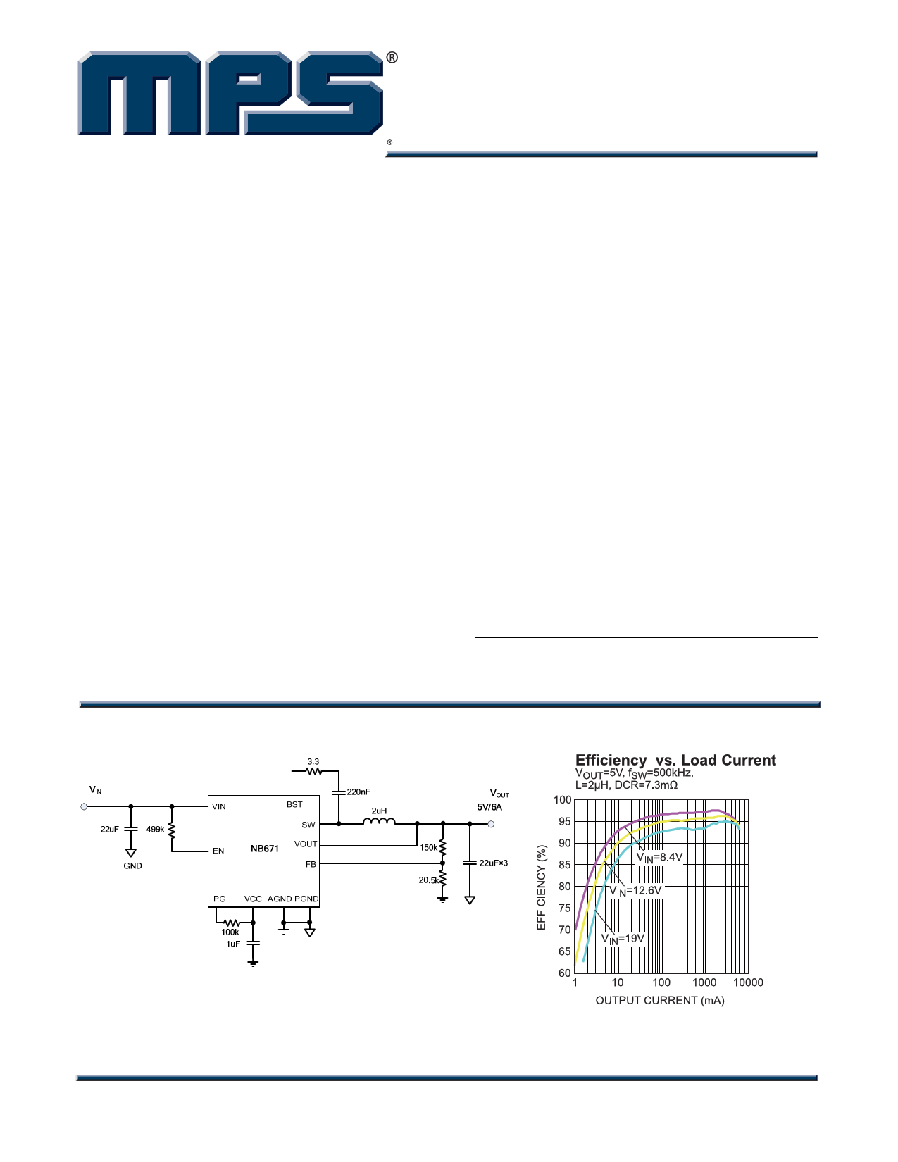
TYPICAL APPLICATION
NB671
24V, High Current
Synchronous Step-down Converter
FEATURES
• Wide 5V to 24V Operating Input Range
• 6A Continuous Output Current
• 9A Peak Output Current
• Low RDS(ON) Internal Power MOSFETs
• Proprietary Switching Loss Reduction
Technique
• 1% Reference Voltage
• 1.7ms Internal Soft Start
• Output Discharge
• 500kHZ Switching Frequency
• OCP, OVP, UVP Protection and Thermal
Shutdown
• Output Adjustable from 0.604V to 5.5V
APPLICATIONS
• Laptop Computer
• Tablet PC
• Networking Systems
• Personal Video Recorders
• Flat Panel Television and Monitors
• Distributed Power Systems
All MPS parts are lead-free and adhere to the RoHS directive. For MPS green
status, please visit MPS website under Products, Quality Assurance page.
“MPS” and “The Future of Analog IC Technology” are registered trademarks of
Monolithic Power Systems, Inc.
NB671 Rev. 1.0
1/14/2013
www.MonolithicPower.com
MPS Proprietary Information. Patent Protected. Unauthorized Photocopy and Duplication Prohibited.
© 2013 MPS. All Rights Reserved.
1
http://www.Datasheet4U.com
1 page 
NB671, 24V, HIGH CURRENT SYNCHRONOUS STEP-DOWN CONVERTER
PIN FUNCTIONS
PIN #
Name
1 VIN
2 PGND
4 PG
3, 5, 6
7 VOUT
NC
8,9
Exposed
Pad 15, 16
SW
10 BST
11 VCC
12 FB
13 EN
14 AGND
Description
Supply Voltage. The IN pin supplies power for internal MOSFET and regulator. The
NB671 operate from a +5V to +22V input rail. An input capacitor is needed to
decouple the input rail. Use wide PCB traces and multiple vias to make the
connection.
Power Ground. Use wide PCB traces and multiple vias to make the connection
Power good output, the output of this pin is an open drain signal and is high if the
output voltage is higher than 95% of the nominal voltage. There is a delay from FB ≥
95% to PGOOD goes high.
VOUT pin is used to sense the output voltage of the Buck regulator, connect this pin
to the output capacitor of the regulator directly.
Switch Output. Connect this pin to the inductor and bootstrap capacitor. This pin is
driven up to the VIN voltage by the high-side switch during the on-time of the PWM
duty cycle. The inductor current drives the SW pin negative during the off-time. The
on-resistance of the low-side switch and the internal diode fixes the negative
voltage. Use wide and short PCB traces to make the connection. Try to minimize the
area of the SW pattern.
Bootstrap. A cap acitor con nected betwe en SW an d BS pins is re quired to form a
floating supply across the high-side switch driver.
Internal 5V LDO output. The driver and control circuits are powered from this
voltage. Decouple with a minimum 1µF ceramic capacitor as close to the pin as
possible. X7R or X5R grade dielectric ceramic capacitors are recommended for their
stable temperature characteristics.
Feedback. An external resistor divider from the output to GND, tapped to the FB pin,
sets the o utput voltage. It is recommended to pla ce the resistor divider as close to
FB pin as possible. Vias should be avoided on the FB traces. It is recommended to
set the current through FB resistors around 10uA.
Enable pin. E N is a di gital input that turn s the regul ator on or off. Drive EN hi gh to
turn on the regulator, drive it low to turn it off. Connect EN with VIN through a pull-up
resistor or a resistive voltage divider for automatic startup. Do not float this pin.
Analog ground. The internal reference is referred to AGND. Connect the GND of the
FB divider resistor to AGND for better load regulation.
NB671 Rev. 1.0
1/14/2013
www.MonolithicPower.com
MPS Proprietary Information. Patent Protected. Unauthorized Photocopy and Duplication Prohibited.
© 2013 MPS. All Rights Reserved.
5
5 Page 
NB671, 24V, HIGH CURRENT SYNCHRONOUS STEP-DOWN CONVERTER
As the output current increases from the light
load condition, the time period within which the
current modulator regulates becomes shorter.
The HS-FET is turned ON more frequently.
Hence, the switching frequency increases
correspondingly. The output current reaches the
critical level when the current modulator time is
zero. The critical level of the output current is
determined as follows:
IOUT
=
(VIN −×VOUT) VOUT
2L×× FSW × VIN
(1)
It turns into PWM mode once the output current
exceeds the critical level. After that, the switching
frequency stays fairly constant over the output
current range.
Jitter and FB Ramp Slope
Jitter occurs in both PWM and skip modes when
noise in the VFB ripple p ropagates a delay to the
HS-FET driver, as sho wn in Figur es 4 and 5 .
Jitter can affect syste m stability, with noise
immunity proportional t o the ste epness of VFB’s
downward slope. However, VFB ripple does no t
directly affect noise immunity.
VNOISE
VSLO PE1
V FB
VREF
H S D river
Jitter
Figure 4—Jitter in PWM Mode
VNOISE
VSLO PE2
V FB
V REF
H S D river
Jitter
Figure 5—Jitter in Skip Mode
Operating without external ramp
The traditio nal con stant-on-time co ntrol scheme
is intrinsically unstable if output capacitor’s ESR
is not large enough as an effective current-sense
resistor. Ce ramic capacitors usually can not be
used as output capacitor.
To realize t he stability, the ESR value should be
chosen as follow:
RESR
≥
TSTW
0.7 ×π
+
COUT
ON
2
TSW is the switching period.
(2)
The NB67 1 has built in int
ernal ramp
compensation to make sure the system is stab le
even without the help of output cap acitor’s ESR;
and thus the pure ceramic capacit or solution can
be applicant. The pure ceramic capacitor solution
can significantly reduce the output ripple, total
BOM cost and the board area.
Figure 6 sh ows a typical output cir cuit in PWM
mode without an external ramp circuit. Turn t o
application information section for design step s
without external compensation.
Figure 6—Simplified Circuit in PWM Mode
without External Ramp Compensation
When using a large-ESR capacitor on the output,
add a cera mic capacitor with a value of 10uF or
less to in parallel to minimize the effect of ESL.
Operating with external ramp compensation
The NB671 is u sually able to support ceramic
output capacitors without external ramp, however,
in some of t he cases, the internal r amp ma y not
be enough to stabilize the system, and external
ramp compensation is need ed. Skip to
application information section for design step s
with external ramp compensation.
NB671 Rev. 1.0
1/14/2013
www.MonolithicPower.com
MPS Proprietary Information. Patent Protected. Unauthorized Photocopy and Duplication Prohibited.
© 2013 MPS. All Rights Reserved.
11
11 Page | ||
| Páginas | Total 20 Páginas | |
| PDF Descargar | [ Datasheet NB671.PDF ] | |
Hoja de datos destacado
| Número de pieza | Descripción | Fabricantes |
| NB670 | 24V High Current Synchronous Buck Converter | MPS |
| NB671 | 24V High Current Synchronous Step-down Converter | MPS |
| NB675 | 24V High Current Synchronous Buck Converter | MPS |
| Número de pieza | Descripción | Fabricantes |
| SLA6805M | High Voltage 3 phase Motor Driver IC. |
Sanken |
| SDC1742 | 12- and 14-Bit Hybrid Synchro / Resolver-to-Digital Converters. |
Analog Devices |
|
DataSheet.es es una pagina web que funciona como un repositorio de manuales o hoja de datos de muchos de los productos más populares, |
| DataSheet.es | 2020 | Privacy Policy | Contacto | Buscar |