|
|
|
PDF AX5511 Data sheet ( Hoja de datos )
| Número de pieza | AX5511 | |
| Descripción | Boost Converter | |
| Fabricantes | AXElite | |
| Logotipo | ||
Hay una vista previa y un enlace de descarga de AX5511 (archivo pdf) en la parte inferior de esta página. Total 9 Páginas | ||
|
No Preview Available !
AX5511
1.2MHz, High Voltage, Boost Converter
GENERAL DESCRIPTION
The AX5511 is a current mode step up converter intended for small, low power
applications. The converter input voltage ranging from 2.6V to 5.5V. The Output voltage can
be set up to 27V. The frequency is 1.2MHz allows the use of small external inductors and
capacitors and provides fast transient response. Internal soft start results in small inrush
current and extends battery life. Internal power MOSFET with very low RDS (ON) provides
high efficiency. The AX5511 automatically transits from PWM to PFM during light load
condition further increasing efficiency. The converter also provides protection functions such
as under-voltage lockout, current limit and thermal shutdown. The AX5511 is available in
5-pin TSOT-23 package.
FEATURES
- 2.6V to 5.5 V operating input voltage range
- Adjustable output voltage range up to 27V
- 1.2MHz Fixed Switching Frequency
- Internal soft-start function
- Current limit and Thermal shutdown protection
- Under voltage Lockout
- ≤ 1µA Shutdown Current
- Available in the 5-pin TSOT-23 Package
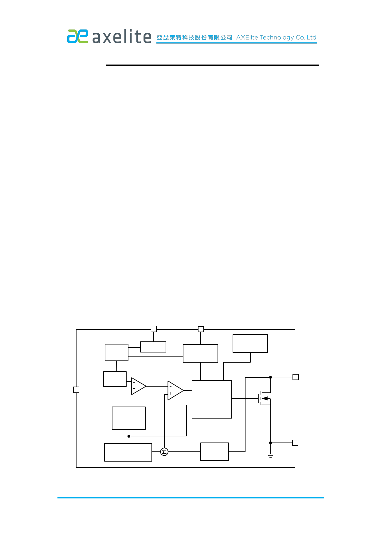
BLOCK DIAGRAM
VCC
EN
Soft
Start
UVLO
Enable/
Disable
Thermal
Shutdown
Vref
1.238V
Summing
Comparator
FB
Error Control and
Amplifier
Driver Logic
Oscillator
1.2MHz
SW
N-MOS
Slope
Compensation
Current
Sense
GND
1/9
Axelite Confidential Materials, do not copy or distribute without written consent.
Rev.1.2 Oct.27, 2011
1 page 
AX5511
Input Capacitor Selection
The input capacitor reduces the surge current drawn from the input and switching
noise from the device. The input capacitor impedance at the switching frequency shall be
less than input source impedance to prevent high frequency switching current passing to the
input. A low ESR input capacitor sized for maximum RMS current must be used. Ceramic
capacitors with X5R or X7R dielectrics are highly recommended because of their low ESR
and small temperature coefficients. A 10µF ceramic capacitor for most applications is
sufficient. For a lower output power requirement application, this value can be decreased.
Output Capacitor Selection
The output capacitor is required to keep the output voltage ripple small and to ensure
regulation loop stability. The output capacitor must have low impedance at the switching
frequency. Ceramic capacitors with X5R or X7R dielectrics are recommended due to their
low ESR and high ripple current. A 4.7uF ceramic capacitors works for most of the
applications. Higher capacitor values can be used to improve the load transient response.
Layout Guide
C1's ground must be as
closer to IC's GND pin as
possible
VCC R4
5
EN
4
C3
C1
VIN
SW should be connected to Inductor by
wide and short trace, keep sensitive
components away from this trace
L1
AX5511
R1
123
SW GND FB R3 R2
C2
VOUT
C2's ground must be as
closer to IC's GND pin as
possible
D1
5/9
Axelite Confidential Materials, do not copy or distribute without written consent.
Rev.1.2 Oct.27, 2011
5 Page | ||
| Páginas | Total 9 Páginas | |
| PDF Descargar | [ Datasheet AX5511.PDF ] | |
Hoja de datos destacado
| Número de pieza | Descripción | Fabricantes |
| AX5510 | Boost Converter | AXElite |
| AX5510A | Boost Converter | AXElite |
| AX5511 | Boost Converter | AXElite |
| AX5511 | Boost Converter | AXElite |
| Número de pieza | Descripción | Fabricantes |
| SLA6805M | High Voltage 3 phase Motor Driver IC. |
Sanken |
| SDC1742 | 12- and 14-Bit Hybrid Synchro / Resolver-to-Digital Converters. |
Analog Devices |
|
DataSheet.es es una pagina web que funciona como un repositorio de manuales o hoja de datos de muchos de los productos más populares, |
| DataSheet.es | 2020 | Privacy Policy | Contacto | Buscar |