|
|
|
PDF HCPL-2531 Data sheet ( Hoja de datos )
| Número de pieza | HCPL-2531 | |
| Descripción | HIGH SPEED TRANSISTOR OPTOCOUPLERS | |
| Fabricantes | QT Optoelectronics | |
| Logotipo | ||
Hay una vista previa y un enlace de descarga de HCPL-2531 (archivo pdf) en la parte inferior de esta página. Total 9 Páginas | ||
|
No Preview Available !
HIGH SPEED
TRANSISTOR OPTOCOUPLERS
SINGLE-CHANNEL
6N135, 6N136
HCPL-2503
HCPL-4502
DESCRIPTION
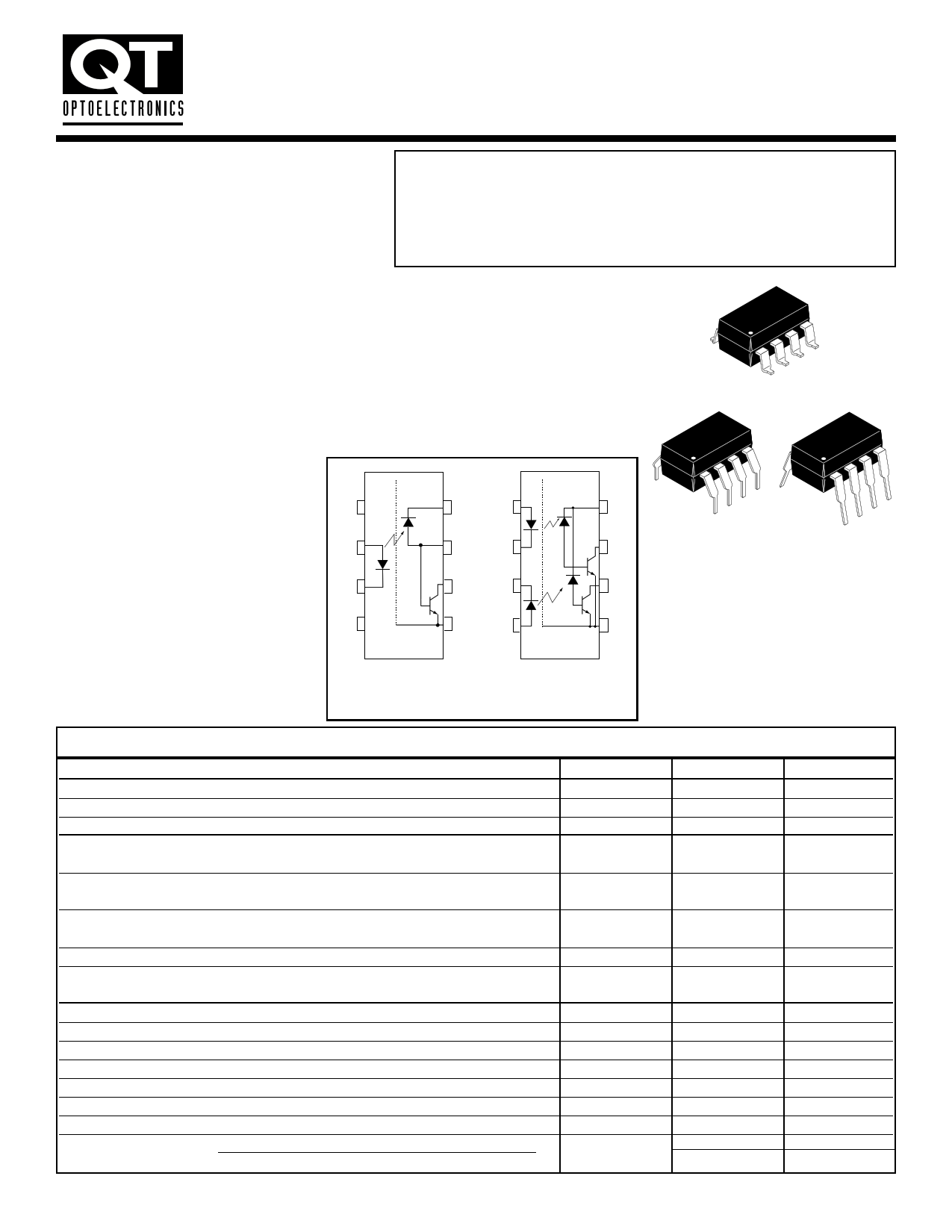
The HCPL-4502/HCPL-2503, 6N135/6 and HCPL-2530/HCPL-2531 optocouplers
consist of an AlGaAs LED optically coupled to a high speed photodetector transistor.
DUAL-CHANNEL
HCPL-2530
HCPL-2531
A separate connection for the bias of the photodiode improves the speed by several
orders of magnitude over conventional phototransistor optocouplers by reducing the
base-collector capacitance of the input transistor.
An internal noise shield provides superior common mode rejection of 10kV/µs. An
improved package allows superior insulation permitting a 480 V working voltage
compared to industry standard 0f 220 V.
8
1
FEATURES
• High speed-1 MBit/s
• Superior CMR-10 kV/µs
• Dual-Channel
HCPL-2530/HCPL-2531
• Double working voltage-480V RMS
• CTR guaranteed 0-70°C
• U.L. recognized (File # E90700)
APPLICATIONS
• Line receivers
• Pulse transformer replacement
• Output interface to CMOS-LSTTL-TTL
• Wide bandwidth analog coupling
N/C 1
+2
V
F
_3
N/C 4
8
V
CC
7
V
B
6V
O
5 GND
6N135, 6N136, HCPL-2503, HCPL-4502
Pin 7 is not connected in
Part Number HCPL-4502
+1
V
F1
_2
_3
V
F2
+4
8
V
CC
8
7
V
01
6
V
02
5 GND
HCPL-2530/HCPL-2531
1
8
1
ABSOLUTE MAXIMUM RATINGS (TA = 25°C unless otherwise specified)
Parameter
Storage Temperature
Operating Temperature
Lead Solder Temperature
EMITTER
DC/Average Forward Input Current
Each Channel (Note 1)
Peak Forward Input Current (50% duty cycle, 1 ms P.W.)
Each Channel (Note 2)
Peak Transient Input Current - (!"1 µs P.W., 300 pps)
Each Channel
Reverse Input Voltage
Each Channel
Input Power Dissipation
(6N135/6N136 and HCPL-2503/4502)
(HCPL-2530/2531 ) Each Channel (Note 3)
DETECTOR
Average Output Current
Each Channel
Peak Output Current
Each Channel
Emitter-Base Reverse Voltage
(6N135, 6N136 and HCPL-2503 only)
Supply Voltage
Output Voltage
Base Current
(6N135, 6N136 and HCPL-2503 only)
Output power
(6N135, 6N136, HCPL-2503, HCPL-4502) (Note 4)
dissipation
(HCPL-2530, HCPL-2531) Each Channel
Symbol
TSTG
TOPR
TSOL
IF (avg)
IF (pk)
IF (trans)
VR
PD
IO (avg)
IO (pk)
VEBR
VCC
VO
IB
PD
Value
-55 to +125
-55 to +100
260 for 10 sec
25
50
1.0
5
100
45
8
16
5
-0.5 to 30
-0.5 to 20
5
100
35
Units
°C
°C
°C
mA
mA
A
V
mW
mA
mA
V
V
V
mA
mW
mW
200004A
1 page 
HIGH SPEED
TRANSISTOR OPTOCOUPLERS
SINGLE-CHANNEL
6N135, 6N136
HCPL-2503
HCPL-4502
DUAL-CHANNEL
HCPL-2530
HCPL-2531
ISOLATION CHARACTERISTICS (TA = 0 to 70°C Unless otherwise specified)
Characteristics
Test Conditions Symbol
Min
Typ**
Max
Unit
(Relative humidity = 45%)
Input-output
insulation leakage current
(TA = 25°C, t = 5 s)
(VI-O = 3000 VDC)
(Note 9)
II-O
1.0 µA
Withstand insulation test voltage
(RH ! 50%, TA = 25°C)
(Note 9) ( t = 1 min.)
VISO
2500
VRMS
Resistance (input to output)
Capacitance (input to output)
(Note 9) (VI-O = 500 VDC)
(Note 9) (f = 1 MHz)
DC Current gain
(IO = 3 mA, VO = 5 V)
Input-Input
(RH ! 45%, VI-I = 500 VDC) (Note 10)
Insulation leakage current t = 5 s, (HCPL-2530/2531 only)
RI-O
CI-O
HFE
II-I
1012
0.6
150
0.005
$
pF
µA
Input-Input Resistance
(VI-I = 500 VDC) (Note 10)
(HCPL-2530/2531 only)
RI-I
1011
$
Input-Input Capacitance
(f = 1 MHz) (Note 10)
(HCPL-2530/2531 only)
CI-I
0.03
pF
** All typicals at TA = 25°C
NOTES
1. Derate linearly above 70°C free-air temperature at a rate of 0.8 mA/°C.
2. Derate linearly above 70°C free-air temperature at a rate of 1.6 mA/°C.
3. Derate linearly above 70°C free-air temperature at a rate of 0.9 mW/°C.
4. Derate linearly above 70°C free-air temperature at a rate of 2.0 mW/°C.
5. Current Transfer Ratio is defined as a ratio of output collector current, IO, to the forward LED input current, IF, times 100%.
6. The 4.1 k$"load represents 1 LSTTL unit load of 0.36 mA and 6.1k$"pull-up resistor.
7. The 1.9 k$"load represents 1 TTL unit load of 1.6 mA and 5.6 k$"pull-up resistor.
8. Common mode transient immunity in logic high level is the maximum tolerable (positive) dVcm/dt on the leading edge of the
common mode pulse signal VCM, to assure that the output will remain in a logic high state (i.e., VO%2.0 V). Common mode transient
immunity in logic low level is the maximum tolerable (negative) dVcm/dt on the trailing edge of the common mode pulse signal, VCM,
to assure that the output will remain in a logic low state (i.e., VO&0.8 V).
9. Device is considered a two terminal device: Pins 1, 2, 3 and 4 are shorted together and Pins 5, 6, 7 and 8 are shorted together.
10. Measured between pins 1 and 2 shorted together, and pins 3 and 4 shorted together.
200004A
5 Page | ||
| Páginas | Total 9 Páginas | |
| PDF Descargar | [ Datasheet HCPL-2531.PDF ] | |
Hoja de datos destacado
| Número de pieza | Descripción | Fabricantes |
| HCPL-2530 | HIGH SPEED TRANSISTOR OPTOCOUPLERS | Fairchild Semiconductor |
| HCPL-2530 | HIGH SPEED TRANSISTOR OPTOCOUPLERS | QT Optoelectronics |
| HCPL-2530 | Single Channel/ High Speed Optocouplers | Agilent(Hewlett-Packard) |
| HCPL-2530 | Dual Channel/ High Speed Optocouplers | Agilent(Hewlett-Packard) |
| Número de pieza | Descripción | Fabricantes |
| SLA6805M | High Voltage 3 phase Motor Driver IC. |
Sanken |
| SDC1742 | 12- and 14-Bit Hybrid Synchro / Resolver-to-Digital Converters. |
Analog Devices |
|
DataSheet.es es una pagina web que funciona como un repositorio de manuales o hoja de datos de muchos de los productos más populares, |
| DataSheet.es | 2020 | Privacy Policy | Contacto | Buscar |