|
|
|
PDF MAX14872 Data sheet ( Hoja de datos )
| Número de pieza | MAX14872 | |
| Descripción | Compact 4.5V to 36V Full-Bridge DC Motor Drivers | |
| Fabricantes | Maxim Integrated | |
| Logotipo | ||
Hay una vista previa y un enlace de descarga de MAX14872 (archivo pdf) en la parte inferior de esta página. Total 15 Páginas | ||
|
No Preview Available !
MAX14870/MAX14872
EVALUATION KIT AVAILABLE
Compact 4.5V to 36V
Full-Bridge DC Motor Drivers
General Description
The MAX14870/MAX14872 motor drivers provide a small,
low-power and simple solution for driving and controlling
brushed DC motors and relays with voltages between
4.5V and 36V. Very low driver on-resistance reduces
power dissipation.
These drivers feature a charge-pump-less design for
reduced external components and low supply current.
Integrated fast-decay current regulation allows user-
adjustable peak startup motor currents and requires mini-
mal external components.
A separate voltage-sense input (SNS) reduces current
sensing errors due to parasitic trace resistance.
The MAX14870/MAX14872 features shoot-through protec-
tion and internal free-wheeling diodes that absorb inductive
motor currents. Driver outputs are short-circuit-protected
from shorts to ground, to the supply, and between M1 and
M2. An active-low FAULT output signals thermal overload
and overcurrents during fault conditions.
The MAX14870 has PWM and direction-control inputs,
while the MAX14872 has forward and reverse inputs for
direction control. See the Function Tables.
The MAX14870/MAX14872 are available in a 12-pin
(3mm x 3mm) TDFN-EP package and operate over the
-40°C to +85°C temperature range.
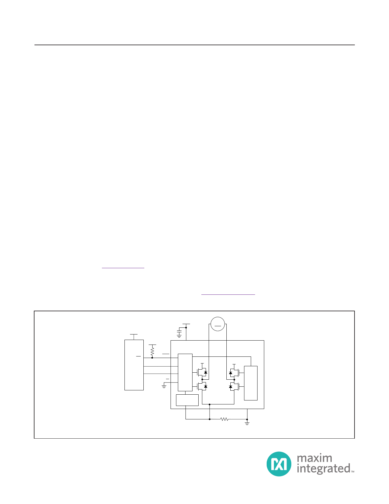
Typical Application Circuit
Benefits and Features
●● Small Package Handles High Power and Reduces
Footprint Circuit Size
• Up to 2.5A Peak Motor Current
• Space-Saving TDFN-EP (3mm x 3mm) Package
• Flexible 4.5V–36V Supply Enables Longer Runtime
on Batteries
●● Low Power Consumption Runs Cooler and Longer
• 280mW (typ) Total Bridge On-Resistance
• 1mA (typ) Supply Current at 30kHz/24V
• 10µA (max) Standby Current at 12V
●● Simplified Designs Reduces Time to Market
• Charge-Pump-Less Architecture
• Current Regulation Only Requires a Sense Resistor
• Current-Sense Input Simplifies PCB Layout
●● Integrated Protection Provides Robust Driving Solution
• Short-Circuit-Protected Drivers
• Thermal-Shutdown Undervoltage Lockout
• Diagnostic FAULT Output
• -40°C to +85°C Temperature Range
Applications
●● Printers and Scanners
●● Relay Drivers
●● Vending and Gaming Machines
Ordering Information appears at end of data sheet.
3.3V
3.3V
IRQ
µC GPO
PWM
FAULT
DIR+
PWM+
EN
24V M
VDD M1
DRIVER
VDD
M2
MAX14870
MAX14872
VDD
DRIVER
CURRENT
REGULATION
SNS
COM
GND
RSENSE
+ THESE PIN NAMES ARE FOR THE MAX14870. ON THE MAX14872, THESE ARE THE FWD AND REV INPUTS.
19-7062; Rev 0; 9/14
1 page 
MAX14870/MAX14872
Test Circuits/Timing Diagrams
M1/ M2
RL
CL
Compact 4.5V to 36V
Full-Bridge DC Motor Drivers
PWM/DIR
FWD/REV
M1/M2
Figure 1. M1/M2 Propagation Delay
1V
tPR
VL
0V
VDD
1V
0V
tPF
IM1 or IM2
IM_OL
FAULT
tOC_BL
tOC_TO
Figure 2. Overcurrent Autoretry Timeout
0A
VL
0V
www.maximintegrated.com
Maxim Integrated │ 5
5 Page 
MAX14870/MAX14872
Compact 4.5V to 36V
Full-Bridge DC Motor Drivers
Detailed Description
The MAX14870/MAX14872 DC brushed motor drivers
provide a low-power and flexible solution for driving and
controlling brushed motors with voltages between 4.5V
and 36V. Peak motor currents of up to 2.5A ensure large
motor torque that is controllable by an external PWM
signal and/or by autonomous internal current regulation.
The MAX14870 has PWM and direction-control inputs,
while the MAX14872 has forward and reverse inputs for
direction control. See Function Tables.
Charge-pump-less design requires minimal external
components and low supply current.
Integrated current regulation allows limiting peak start-
up motor currents. Shoot-through protection with a
140ns (typ) dead time ensures low operating current.
Internal free-wheeling diodes absorb inductive motor cur-
rents. The FAULT output signals thermal overload and
overcurrents.
Overcurrent Protection
The MAX14870/MAX14872 are protected against shorts
on M1/M2 to any voltage between VDD and GND, includ-
ing shorts to GND, VDD, and between M1 and M2 via
overcurrent limiting. When a current above 6A (typ)
flows through M1 or M2 for longer than 1µs, an overcur-
rent condition is detected and the H-bridge drivers are
automatically disabled and the FAULT output asserts.
If the overcurrent condition continues for longer than the
overcurrent autoretry timeout (2ms (typ)) the MAX14870/
MAX14872 enters autoretry mode. In autoretry mode,
the M1 and M2 outputs are re-enabled for 1µs (typ) and
FAULT goes high-impedance. The drivers are disabled
again and FAULT is re-asserted if the overcurrent condi-
tion persists.
PWM Control (MAX14870 only)
The PWM input is used for motor speed/torque control.
Increasing or decreasing the duty cycle at PWM sets the
effective (average) voltage across the motor terminals
and allows first-order speed control.
When PWM is logic-high, the motor is driven in the direc-
tion defined by DIR. When PWM is logic-low, the bridge
is in brake mode. In brake mode, the motor current
continues flowing and recirculates through the low-side
transistors of the H-bridge driver, due to its inductive
impedance and back EMF.
FWD/REV Control (MAX14872 only)
The FWD input is used to drive the motor forward/turn a
relay on. The REV input reverses the M1 and M2 polarity,
to drive the motor in reverse/turn a relay off.
FWD/REV control can be optionally used to implement
either bipolar motor control (with both M1 and M2 switch-
ing) or unipolar control, where only M1 or M2 switches.
Slope Control
The MAX14871 drivers turn-on and turn-off with active
slope-control during the M1/M2 transition times. The
integrated slew rate-limiting reduces EMC (like conducted
and radiated EMI) associated with high di/dt rates.
Thermal Shutdown
The MAX14870/MAX14872 include integrated protection
against thermal overload. When the junction temperature
exceeds 160°C (typ), the H-bridge is tri-stated, M1 and
M2 are disabled, and FAULT is asserted.
If the motor was spinning before thermal shutdown
occurred, the motor’s inductance will push current through
the internal M1 and M2 diodes, forcing the motor into fast
decay, with a voltage across its terminals of VDD.
M1 and M2 are automatically re-enabled when the
junction temperature falls to 150°C (typ).
Current Sensing
Connect a sense resistor (RSENSE) between COM
and GND to monitor the motor current during operation.
Select RSENSE such that the voltage at COM created by
motor current flowing through the sense resistor is limited
to within 250mV relative to GND (-250mV ≤ VCOM ≤
+250mV).
Minimize series trace resistance from RSENSE to GND
to minimize voltage sense errors due to parasitic trace
interconnect resistance. Use a star ground connection
between the MAX14870/MAX14872 GND pins and the
GND-side of RSENSE. Connect the voltage sense close
to the RSENSE resistor and/or use differential voltage
sensing. See Figure 4.
www.maximintegrated.com
Maxim Integrated │ 11
11 Page | ||
| Páginas | Total 15 Páginas | |
| PDF Descargar | [ Datasheet MAX14872.PDF ] | |
Hoja de datos destacado
| Número de pieza | Descripción | Fabricantes |
| MAX1487 | Low-Power / Slew-Rate-Limited RS-485/RS-422 Transceivers | Maxim Integrated |
| MAX14870 | Compact 4.5V to 36V Full-Bridge DC Motor Drivers | Maxim Integrated |
| MAX14871 | 4.5V to 36V Full-Bridge DC Motor Driver | Maxim Integrated |
| MAX14872 | Compact 4.5V to 36V Full-Bridge DC Motor Drivers | Maxim Integrated |
| Número de pieza | Descripción | Fabricantes |
| SLA6805M | High Voltage 3 phase Motor Driver IC. |
Sanken |
| SDC1742 | 12- and 14-Bit Hybrid Synchro / Resolver-to-Digital Converters. |
Analog Devices |
|
DataSheet.es es una pagina web que funciona como un repositorio de manuales o hoja de datos de muchos de los productos más populares, |
| DataSheet.es | 2020 | Privacy Policy | Contacto | Buscar |