|
|
|
PDF NCT75 Data sheet ( Hoja de datos )
| Número de pieza | NCT75 | |
| Descripción | Industry Standard Digital Temperature Sensor | |
| Fabricantes | ON Semiconductor | |
| Logotipo | ||
Hay una vista previa y un enlace de descarga de NCT75 (archivo pdf) en la parte inferior de esta página. Total 15 Páginas | ||
|
No Preview Available !
NCT75
Industry Standard Digital
Temperature Sensor with
2‐wire Interface
The NCT75 is a two-wire serially programmable temperature
sensor with an over-temperature/interrupt output pin to signal out of
limit conditions. This is an open-drain pin and can operate in either
comparator or interrupt mode. Temperature measurements are
converted into digital form using a high resolution (12 bit),
sigma-delta, analog-to-digital converter (ADC). The device operates
over the –55°C to +125°C temperature range.
Communication with the NCT75 is accomplished via the
SMBus/I2C interface. Three address selection pins, A2, A1 and A0,
can be used to connect up to 8 NCT75s to a single bus. Through this
interface the NCT75s internal registers may be accessed. These
registers allow the user to read the current temperature, change the
configuration settings and adjust the temperature limits.
The NCT75 has a wide supply voltage range of 3.0 V to 5.5 V. The
average supply current is 575 mA at 3.3 V. It also offers a shutdown
mode to conserve power. The typical shutdown current is 3 mA.
The NCT75 is available in three, space saving packages – 8-lead
DFN, 8-lead Micro8t and 8-lead SOIC and is also fully pin and
register compatible with the LM75 and TCN75.
Features
• 12-bit Temperature-to-Digital Converter
• Input Voltage Range from 3.0 V to 5.5 V
• Temperature Range from −55°C to +125°C
• SMBus/I2C Interface
• Overtemperature Indicator
• Support for SMBus/ALERT
• Shutdown Mode for Low Power Consumption
• One-shot Mode
• Available in 8-pin DFN, 8-pin Micro8t and SOIC Packages
• These Devices are Pb-Free, Halogen Free/BFR Free and are RoHS
Compliant
Applications
• Computer Thermal Monitoring
• Thermal Protection
• Isolated Sensors
• Battery Management
• Office Electronics
• Electronic Test Equipment
• Thermostat Controls
• System Thermal Management
http://onsemi.com
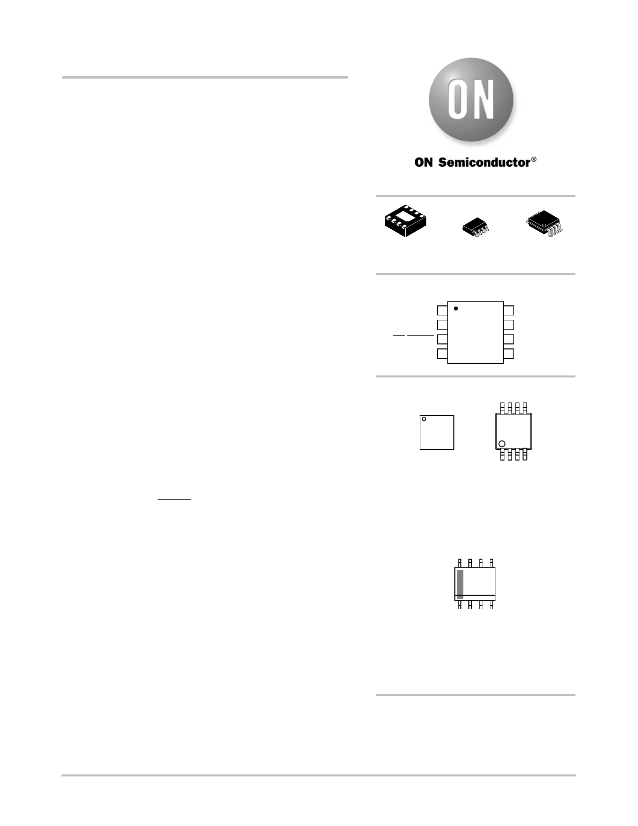
DFN8
CASE 506AA
SOIC8
CASE 751
Micro8t
CASE 846A
PIN ASSIGNMENT
SDA 1
SCL 2
OS/ALERT 3
GND 4
(Top View)
8 VDD
7 A0
6 A1
5 A2
MARKING DIAGRAMS
1
75MG
G
DFN8
8
CT75
AYWG
G
1
Micro8t
M = Date Code
A = Assembly Location
Y = Year
W = Work Week
G = Pb-Free Package
(Note: Microdot may be in either location)
8
NCT75
ALYWX
G
1
SOIC8
A = Assembly Location
L = Wafer Lot
Y = Year
W = Work Week
G = Pb-Free Package
ORDERING INFORMATION
See detailed ordering and shipping information in the package
dimensions section on page 12 of this data sheet.
© Semiconductor Components Industries, LLC, 2014
May, 2014 − Rev. 6
1
Publication Order Number:
NCT75/D
1 page 
NCT75
APPLICATION INFORMATION
Functional Description
The NCT75 temperature sensor converts an analog
temperature measurement to a digital representation by
using an on-chip measurement transistor and a 12 bit
Delta-Sigma ADC.
The device includes an open drain ALERT output which
can be used to signal that the programmed temperature limit
has been exceeded.
The two main modes of operation are normal and
shutdown mode. In normal mode the NCT75 performs
a new temperature conversion every 80 ms. This new value
is then updated to the temperature value register
(address 0x00) and also compared to the TOS register limit
(default = 80°C). If the temperature value register is read
during the conversion sequence the value returned is the
previously stored value. A bus read does not affect the
conversion that is in progress.
In shutdown mode temperature conversion is disabled and
the temperature value register holds the last valid
temperature reading. The NCT75 can still be communicated
with in this mode as the interface is still active. The device
mode is controlled via bit 0 of the configuration register.
While in shutdown mode a conversion can be initiated by
writing an arbitrary value to the one-shot register (0x04).
This has the effect of powering up the NCT75, performing
a conversion, comparing the new temperature with the
programmed limit and then going back into shutdown mode.
The OS/ALERT pin can be configured in many ways to
allow it to be used in many different system configurations.
The overtemperature output can be configured to operate
as a comparator type output (which is self clearing once the
temperature has returned below the hysteresis value) or an
interrupt type output (which requires the master to read an
internal register AND the temperature to return below the
hysteresis value before going into an inactive state). The
ALERT pin can also be configured as an active high or active
low output.
Temperature Measurement Results
The results of the on chip temperature measurements are
stored in the temperature value register and compared with
the TOS and THYST limit register.
The temperature value, TOS and THYST registers are
16 bits wide and have a resolution of 0.0625°C. The data is
stored as a 12 bit 2s complement word. The data is left
justified, D15 is the MSB and is the sign bit. The four LSBs
(D3 to D0) are always 0 as they are not part of the result.
While the ADC of the NCT75 can theoretically measure
temperatures in the range of −128°C to 127°C, the NCT75
is guaranteed to measure from −55°C to +125°C.
Table 6 shows the relevant temperature bits for a 12 bit
temperature reading. A 2-byte read is required to obtain the
full 12 bit temperature reading. If an 8 bit (1°C resolution)
reading is required then a single byte read is sufficient.
Table 6. 12-BIT TEMPERATURE DATA FORMAT
Temperature
Binary Value
D15 to D4
Hex Value
−55°C
1100 1001 0000
0xC90
−25°C
1110 0111 0000
0xE70
−0.0625°C
1111 1111 1111
0xFFF
0°C
0000 0000 0000
0x000
+0.0625°C
0000 0000 0001
0x001
+25°C
0001 1001 0000
0x190
+75.25°C
0100 1011 0100
0x4B4
+100°C
0110 0100 0000
0x640
+125°C
0111 1101 0000
0x7D0
Temperature Data Conversion
12-bit Temperature Data Format
Positive Temperature = ADC Code (decimal)/16
Example 190h = 400d/16 = +25°C
Negative Temperature = (ADC Code(decimal) − 4096)/16
Example E70h = (3696d – 4096)/16 = −25°C
One-shot Mode
One of the features of the NCT75 is a One-shot
Temperature Measurement Mode. This mode is useful if
reduced power consumption is a design requirement.
To enable one-shot mode bit 5 of the configuration
register needs to be set. Once, enabled, the NCT75 goes
immediately into shutdown mode. Here, the current
consumption is reduced to a typical value of 3 mA. Writing
address 0x04 to the address pointer register initiates a
one-shot temperature measurement. This powers up the
NCT75, carries out a temperature measurement, and then
powers down again. The data written to this register is
irrelevant and is not stored. It is the write operation that
causes the one-shot conversion.
http://onsemi.com
5
5 Page 
NCT75
Reading Data
Reading data from the NCT75 is done in two different
ways depending on the register being read. The
configuration register is only 8 bits wide so a single byte
read is used for this (shown in Figure 8). This consists of the
device address followed by the data from the register.
Reading the data in the temperature value register requires
a two byte read (shown in Figure 9). This consists of the
device address, followed by two bytes of data from the
temperature register (the first byte is the MSB). In both cases
the address pointer register of the register being read must
be written to prior to performing a read operation.
OS/ALERT Output Overtemperature Modes
The OS/ALERT output pin can operate in two different
modes – overtemperature mode and SMBus alert mode. The
pin defaults to overtemperature mode on power up. This
means that it becomes active when the measured
temperature meets or exceeds the limit stored in the TOS
setpoint register. At this point it can deal with the event in
one of two ways which depends on the mode it is in. The two
overtemperature modes are: comparator mode and interrupt
mode. Comparator mode is the default mode on power up.
More information on comparator and interrupt modes
alsong with the SMBus alert mode are explained below.
Comparator Mode
In Comparator Mode, the OS/ALERT pin becomes active
when the measured temperature equals or exceeds the limit
stored in the TOS setpoint register. The pin returns to its
inactive status when the temperature drops below the THYST
setpoint register value.
NOTE: Shutdown mode does not reset the output state for
comparator mode.
Interrupt Mode
In the interrupt mode, the OS/ALERT pin becomes active
when the temperature equals or exceeds the TOS limit for
a consecutive number of faults. It can be reset by performing
a read operation on any register in the NCT75. The output
can only become active again when the TOS limit has been
equalled or exceeded.
Figure 11 shows how both the interrupt and comparator
modes operate in relation to the output pin (OS/ALERT). It
also shows the operation of the polarity bit in the
configuration register.
http://onsemi.com
11
11 Page | ||
| Páginas | Total 15 Páginas | |
| PDF Descargar | [ Datasheet NCT75.PDF ] | |
Hoja de datos destacado
| Número de pieza | Descripción | Fabricantes |
| NCT72 | Temperature Monitor | ON Semiconductor |
| NCT75 | Industry Standard Digital Temperature Sensor | ON Semiconductor |
| NCT7511Y | H/W Monitoring IC | nuvoton |
| NCT7717U | Thermal Sensor IC | nuvoton |
| Número de pieza | Descripción | Fabricantes |
| SLA6805M | High Voltage 3 phase Motor Driver IC. |
Sanken |
| SDC1742 | 12- and 14-Bit Hybrid Synchro / Resolver-to-Digital Converters. |
Analog Devices |
|
DataSheet.es es una pagina web que funciona como un repositorio de manuales o hoja de datos de muchos de los productos más populares, |
| DataSheet.es | 2020 | Privacy Policy | Contacto | Buscar |