|
|
|
PDF GP2W0001 Data sheet ( Hoja de datos )
| Número de pieza | GP2W0001 | |
| Descripción | Low Power Infrared Transceiver | |
| Fabricantes | Sharp Electrionic Components | |
| Logotipo | ||
Hay una vista previa y un enlace de descarga de GP2W0001 (archivo pdf) en la parte inferior de esta página. Total 15 Páginas | ||
|
No Preview Available !
IrDA Data Sheet
GP2W0001YP
115 kbps Transceiver
FEATURES
• Built-in Photodiode
• Operating voltage 2.7 V to 5.5 V
• In circuit design, allow for the degradation of light
emitting diode output that results from long continu-
ous operation (50% degradation/5 years).
• This product shall not contain the following materi-
als, and these materials shall not be used in the pro-
duction process for this product.
– CFCs
– Halon
– Carbon Tetrachloride
– 1.1.1. Trichloroethane (Methylchloroform)
– Specific brominated flame retardants such as the
PBBOs and PBBs are not used in this device.
INTRODUCTION
This specification applies to the outline and charac-
teristics of IrDA 1.2 type (data rate 2.4 kbps to
115.2 kbps, low power option compliant) optical data
communication transceiver.
NOTES
• Caution should be taken to prevent the detector sur-
face from being smeared with dust or dirt, or from
being touched, as it may cause faulty operation.
• Cleaning conditions:
– Solvent cleaning: Solvent temperature 45°C or
less. Immersion for 3 minutes or less.
– Ultrasonic cleaning: The effect of ultrasonic
cleaning on the device differs by cleaning bath
size, ultrasonic power output, cleaning time, PCB
size or device mounting condition, etc. Test the
device under actual conditions and confirm that
ultrasonic cleaning does not cause any immedi-
ate or potential defects.
– Cleaning solvent: The cleaning shall be carried
out with ethyl alcohol, methyl alcohol, or isopropyl
alcohol.
• In order to prevent electrostatic damage to the inte-
grated circuit, handle this device in a static-free envi-
ronment and workstation.
• External force applied to the device after mounting can
cause mounting defects such as the terminal coming
off. Be careful when handling the device and prevent
objects from touching the device after mounting.
• Refer to the ‘Precautions for Soldering’ section.
• When the system (program) is designed, the turn
around time from transmit to receive should be
designed by considering 0.5 ms or more that is spec-
ified by IrDA. This turn around time means the time
that this device temporarily does not detect the
incoming signal, since the transmitted light from the
transmitter side reaches the detector side of the
same transceiver.
• Consider that 20 ms or more (at TA = 25°C, no input
signal) is necessary to return from shut-down mode
to ready operation mode. In addition, thoroughly
confirm the operation in the actual application.
• When there is considerable external stray light or a
light source is located near the transceiver, or the
detector face receives considerable external stray
light, a pulse other than the desired signal output may
be generated as noise on the output terminal of the
transceiver. Consider the layout and structure in your
design to minimize disturbing light on the detector face.
• When the sensor is adopted in an IR communication
system, it should be used according to the signal
method specified by ‘Serial Infrared Physical Layer
Link Specification’ published by the Infrared Data
Association. Faulty operation may occur if a signal
method other than that specified is used.
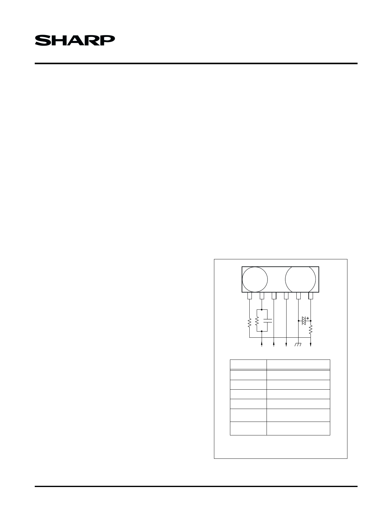
1 23 456
LEDA TXD SD RXD GND VCC
R2
RL
CX2
CX1
R1
TX SD RXD
VCC
COMPONENTS RECOMMENDED VALUES
CX1 47 µF/6.3 V (NOTE)
CX2 1500 pF/25 V
R1 47 Ω ±5%, 1/10 W (NOTE)
R2
RL
(STANDARD)
RL
(LOW POWER)
1 kΩ ±5%, 1/10 W
2.2 Ω ±5%, 1/2 W
(VCC = 3.0 V, IE = 40 mW/sr)
33 Ω ±1%, 1/8 W
(VCC = 3.0 V, IE = 3.6 mW/Sr)
NOTE: Choose the most suitable CX1 and R1 according to
the noise level and noise frequency of power supply.
GP2W0001YP-1
Figure 1. Recommended External Circuit
IrDA Data Sheet
1
1 page 
115 kbps Transceiver
RATINGS AND CHARACTERISTICS
Absolute Maximum Ratings
PARAMETER
SYMBOL
Supply voltage
Forward current
Peak forward current
Operating temperature
Storage temperature
Soldering temperature
VCC
IF
IFM
TOPR
TSTG
TSOL
NOTES:
1. Pulse width: 78.1 µs. Duty ratio: 3/16.
2. Soldering reflow time: 5 seconds.
RATINGS
0 to 6.0
50
500
-10 to +70
-20 to +85
230
UNIT
V
mA
mA
°C
°C
°C
NOTES
1
2
Recommended Operating Conditions
PARAMETER
Supply voltage
Data rate
Shutdown circuit high level input voltage
Shutdown circuit low level input voltage
Logic high transmitter input voltage*
Logic low receiver input voltage*
NOTES: *Recommended circuit of emitter side.
SYMBOL
VCC
BR
VIHSD
VILSD
VIHTXD
VILTXD
OPERATING CONDITION
2.7 to 5.5
2.4 to 115.2
VCC – 0.6 to VCC
0.0 to 0.4 or Open
2.4 to VCC
0.0 to 0.4
UNIT
V
kbps
V
V
V
V
GP2W0001YP
IrDA Data Sheet
5
5 Page 
115 kbps Transceiver
GP2W0001YP
TAPING SPECIFICATIONS
Taping Method
• Taping structure and dimensions: The tape should
have a structure in which a cover tape is sealed by
using heat-pressed on the carrier tape of conductive
PET. See Figure 14.
• Reel structure and dimensions: The taping reel
should be conductive plastic with its dimensions as
shown in Figure 15.
• Direction of product insertion: Product direction in
carrier tape should be such that electrode side of
product is placed on the cover tape side and lens
side of product is placed on the hold side of the tape.
See Figure 16.
• Taped device repair: To repair taped device failure,
cut the bottom of carrier tape with a cutter, and after
replacing with good devices, seal the cut portion with
adhesive tape.
• Adhesiveness of cover tape: The exfoliation force
between carrier tape and cover tape should be 0.2 N
to 1 N for the angle from 160° to 180°.
• Rolling method and quantity: Wind the tape back on
the reel so that the cover tape is on the outside.
Attach more than 20 cm of blank tape to the trailer
and the leader of the tape and fix both ends with
adhesive tape. One reel shall contain 2,000 pieces.
• Safety protection during shipping: There should be
no deformation of component or degradation of elec-
trical characteristics due to shipping.
2.0 ±0.1
4.0 ±0.1
8.0 ±0.1
φ1.5
+0.1
-0.0
3.5 ±0.1
0.3 ±0.05
4.8 ±0.25
4.1 ±0.25
7° MAX.
NOTE: Dimensions are in mm.
Figure 14. Tape Structure and Dimensions
GP2W0001YP-14
IrDA Data Sheet
11
11 Page | ||
| Páginas | Total 15 Páginas | |
| PDF Descargar | [ Datasheet GP2W0001.PDF ] | |
Hoja de datos destacado
| Número de pieza | Descripción | Fabricantes |
| GP2W0001 | IrDA Data Sheet 115 kbps Transceiver | Sharp Electrionic Components |
| GP2W0001 | Low Power Infrared Transceiver | Sharp Electrionic Components |
| GP2W0001YP | IrDA Data Sheet 115 kbps Transceiver | Sharp Electrionic Components |
| GP2W0001YP | Low Power Infrared Transceiver | Sharp Electrionic Components |
| Número de pieza | Descripción | Fabricantes |
| SLA6805M | High Voltage 3 phase Motor Driver IC. |
Sanken |
| SDC1742 | 12- and 14-Bit Hybrid Synchro / Resolver-to-Digital Converters. |
Analog Devices |
|
DataSheet.es es una pagina web que funciona como un repositorio de manuales o hoja de datos de muchos de los productos más populares, |
| DataSheet.es | 2020 | Privacy Policy | Contacto | Buscar |