|
|
|
PDF HDSP-4836 Data sheet ( Hoja de datos )
| Número de pieza | HDSP-4836 | |
| Descripción | 10-Element Bar Graph Array | |
| Fabricantes | AVAGO | |
| Logotipo | ||
Hay una vista previa y un enlace de descarga de HDSP-4836 (archivo pdf) en la parte inferior de esta página. Total 6 Páginas | ||
|
No Preview Available !
HDSP-4830/4840/4850, HDSP-4832/4836 & HLCP-J100
10-Element Bar Graph Array
Data Sheet
Description
These 10-element LED arrays are designed to display
information in easily recognizable bar graph form. The
packages are end stackable and therefore capable of
displaying long strings of information. Use of these bar
graph arrays eliminates the alignment, intensity, and
color matching problems associated with discrete LEDs.
The HDSP-4830/4840/4850 and HLCPJ100 each contain
LEDs of one color. The HDSP-4832/4836 are multicolor
arrays with High Efficiency Red, Yellow, and High Perfor-
mance Green LEDs in a single package.
Applications
• Industrial Controls
• Instrumentation
• Office Equipment
• Computer Peripherals
• Consumer Products
Features
• Custom Multicolor Array Capability
• Matched LEDs for Uniform Appearance
• End Stackable
• Package Interlock Ensures Correct Alignment
• Low Profile Package
• Rugged Construction
• Large, Easily Recognizable Segments
• High ON-OFF Contrast, Segment to Segment
• Wide Viewing Angle
• Categorized for Luminous Intensity
• HDSP-4832/4836/4840/4850 Categorized for Domi-
nant Wavelength
• HLCP-J100 Operates at Low Current
Typical Intensity of 1.0 mcd at 1 mA Drive Current
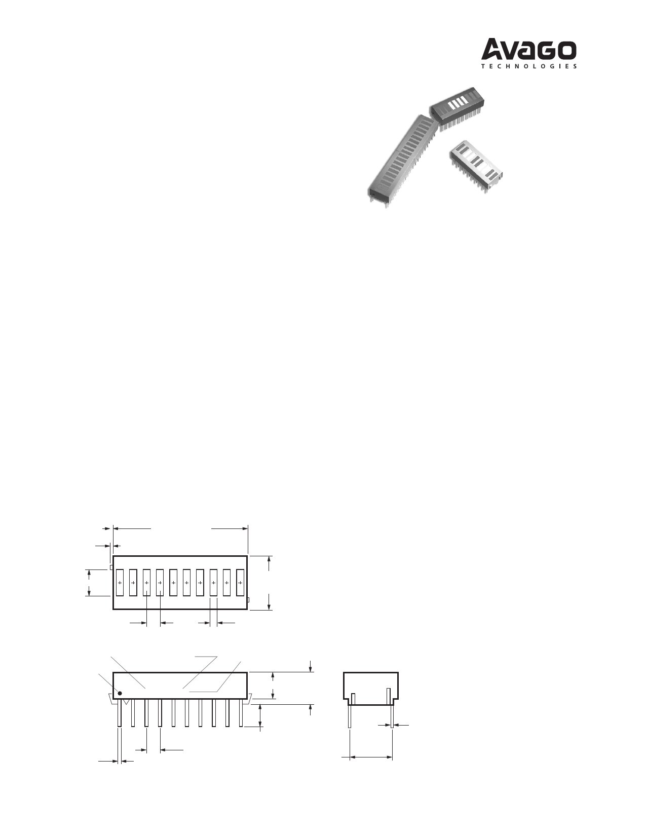
Package Dimensions
0.38
(0.015)
5.08 (0.200)
25.40 (1.000) MAX.
10.16
(0.400)
MAX.
1. DIMENSIONS IN MILLIMETERS (INCHES).
2. ALL UNTOLERANCED DIMEMSIONS FOR
REFERENCE ONLY.
3. HDSP-4832/-4836/-4840/-4850 ONLY.
2.54
(0.100)
DATE CODE
PIN ONE
MARKING
LUMINOUS
INTENSITY
CATEGORY
HDSP XXXX
XYY ZW
1.52
(0.060)
COLOR BIN
(NOTE 3)
6.10 ± 0.25
(0.240 ± 0.010)
5.08 (0.200)
0.61
(0.024)
2.54 ± 0.25
(0.100 ± 0.010)
4.06
(0.160)
MIN.
7.62 ± 0.38
(0.300 ± 0.015)
0.38
(0.015)
1 page 
HER, Yellow, Green
20
15 GREEN
1120
8 HER
6
YELLOW
4
3
OPERATION IN
THIS REGION
REQUIRES
TEMPERATURE
DERATING OF
IDC MAX
2
1.5
1
1
1 0 100 1000
tP - PULSE DURATION - µSEC
10000 DC OPERATION
Figure 8. Maximum Tolerable Peak Current vs. Pulse Duration –
HER/Yellow/Green.
40
35
30 GREEN/HER
25 GREEN
20 YELLOW
15
R θJ-A= 600°C/W
HER
YELLOW
10
5
0
15 25
35 45 55 65 75 85
TA - AMBIENT TEMPERATURE - °C
95
Figure 9. Maximum Allowable DC Current vs.
Ambient Temperature. TJMAX = 100°C.
1.6
1.5 YELLOW SERIES
1.4 HER SERIES
1.3
1.2 GREEN SERIES
1.1
1.0
0.9
0.8
0.7
0.6
0 10 20 30 40 50 60 70 80 90 100
IPEAK - PEAK SEGMENT CURRENT - mA
Figure 10. Relative Efficiency (Luminous Intensity
per Unit Current) vs. Peak Current.
90
80
70
60
50
40
30
20
10
0
1.0
GREEN SERIES
HER
SERIES
YELLOW SERIES
2.0 3.0 4.0
VF - FORWARD VOLTAGE - V
5.0
Figure 11. Forward Current vs. Forward Voltage.
4.0
3.5
3.0
2.5
2.0
1.5
1.0
0.5
0
0 53 10 15 20 25 30 5 40
IF - FORWARD CURRENT PER SEGMENT - mA
Figure 12. Relative Luminous Intensity vs. DC
Forward Current.
For a Detailed Explanation on the Use of Data Sheet Information and Recommended Soldering Procedures,
See Application Note 1005.
5
5 Page | ||
| Páginas | Total 6 Páginas | |
| PDF Descargar | [ Datasheet HDSP-4836.PDF ] | |
Hoja de datos destacado
| Número de pieza | Descripción | Fabricantes |
| HDSP-4830 | (HDSP-48xx) 10-Element Bar Graph Array | Hewlett-Packard |
| HDSP-4830 | (HDSP-48xx) 10-Element Bar Graph Array | AVAGO TECHNOLOGIES |
| HDSP-4832 | (HDSP-48xx) 10-Element Bar Graph Array | Hewlett-Packard |
| HDSP-4832 | (HDSP-48xx) 10-Element Bar Graph Array | AVAGO TECHNOLOGIES |
| Número de pieza | Descripción | Fabricantes |
| SLA6805M | High Voltage 3 phase Motor Driver IC. |
Sanken |
| SDC1742 | 12- and 14-Bit Hybrid Synchro / Resolver-to-Digital Converters. |
Analog Devices |
|
DataSheet.es es una pagina web que funciona como un repositorio de manuales o hoja de datos de muchos de los productos más populares, |
| DataSheet.es | 2020 | Privacy Policy | Contacto | Buscar |