|
|
|
PDF NCL30105 Data sheet ( Hoja de datos )
| Número de pieza | NCL30105 | |
| Descripción | Constant Off Time PWM Current-Mode Controller | |
| Fabricantes | ON Semiconductor | |
| Logotipo | ||
Hay una vista previa y un enlace de descarga de NCL30105 (archivo pdf) en la parte inferior de esta página. Total 22 Páginas | ||
|
No Preview Available !
NCL30105
Constant Off Time PWM
Current-Mode Controller for
LED Applications
The NCL30105 is a peak current controlled fixed off time controller
designed for LED driver applications in which the LEDs are operated
in deep Continuous Conduction Mode (CCM) without requiring slope
compensation. Featuring an adjustable off time generator, the
controller can drive a MOSFET up to a 500 kHz switching frequency.
A dedicated dimming pin enables the use of a pulse−width
modulated logic signal to dim the LEDs directly. The soft−start pin
creates a startup sequence that slowly ramps up the peak current and
enables the adjustment of the peak current setpoint for analog
dimming control. The device features robust protection features to
detect switch overcurrent faults and to detect maximum on time
events.
Features
• Constant Off Time Current−Mode Control Operation
• Adjustable Off Time (0.5 ms to 10 ms)
• Internal Leading Edge Blanking
• Source 250 mA / Sink 500 mA Peak Drive Capability
• ±3.2% Current Sense Accuracy at 25°C
• Internal Startup Delay
• 3.3 V Logic Level Dimming Input
• This is a Pb−Free Device
Safety Features
• Thermal Shutdown
• Maximum On Time Protection
• Overcurrent Protection
Typical Application
• LED Backlight Drivers for LCD Panels
• LED Light Bars
• LED Street Lighting
• LED Bulbs
http://onsemi.com
8
1
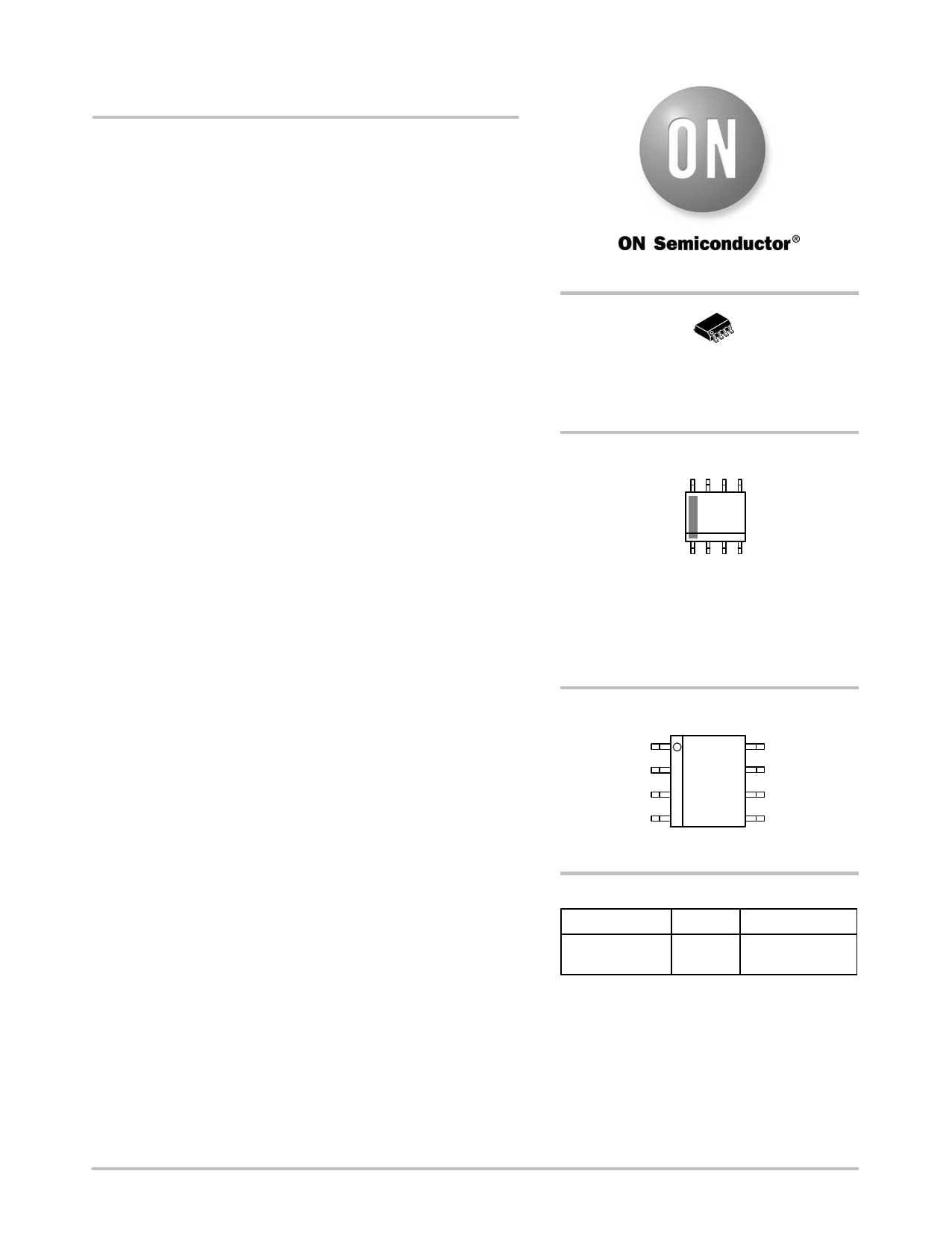
SOIC−8
D SUFFIX
CASE 751
MARKING DIAGRAM
8
L0105
ALYW
G
1
L0105
A
L
Y
W
G
= Specific Device Code
= Assembly Location
= Wafer Lot
= Year
= Work Week
= Pb−Free Package
PIN CONNECTIONS
1
toff
DIM
NC
SSTART
VCC
CS
GND
DRV
(Top View)
ORDERING INFORMATION
Device
Package
Shipping†
NCL30105DR2G SOIC−8 2500 / Tape & Reel
(Pb−Free)
†For information on tape and reel specifications,
including part orientation and tape sizes, please
refer to our Tape and Reel Packaging Specifications
Brochure, BRD8011/D.
© Semiconductor Components Industries, LLC, 2012
May, 2012 − Rev. 2
1
Publication Order Number:
NCL30105/D
1 page 
NCL30105
Table 3. ELECTRICAL CHARACTERISTICS (Rtoff = 40.2 kW, VDIM = 3 V, CSSTART = 100 nF, VCS = 0 V, CDRV = 1 nF, VCC = 12 V,
unless otherwise specified (For typical values, TJ = 25°C. For min/max values, TJ = −40°C to 125°C, unless otherwise specified))
Characteristic
Test Conditions
Symbol
Min Typ Max Unit
STARTUP AND SUPPLY CIRCUITS
Startup Voltage Threshold
Minimum Operating Voltage
Supply Voltage Hysteresis
Current Consumption in Latch Mode
Startup Current Consumption
Device Disabled Current Consumption
Device Switching Current Consumption
GATE DRIVE
VCC Increasing
VCC Decreasing
VCC(on) − VCC(off)
VCC < VCC(on) − 500 mV
VDIM = 0 V
fSW = 60 kHz
VCC(on)
VCC(off)
VCC(HYS)
ICC(latch)
ICC1
ICC2
ICC3
9 10 11 V
8 8.8 10 V
1 1.2 1.5 V
−
510 900
mA
−
250 390
mA
− 0.71 1.7 mA
−
1.84 2.49
mA
Drive Sink Resistance
Drive Source Resistance
Rise Time
Fall Time
CURRENT SENSE
ISNK = 25 mA
ISRC = 25 mA
VDRV = 10% to 90%
VDRV = 90% to 10%
RSNK
RSRC
tr
tf
−
6.0 13.2
W
− 24 44 W
− 80 140 ns
− 25 60 ns
Current Sense Voltage Threshold
TJ =−40°C to 125°C
TJ =25°C
Current Sense Propagation Delay
Leading Edge Blanking Duration
VCS = 0 V to 1.2 V Step,
dV/dt = 10 V/ms
VCS = VILIM to VDRV = 10%
CONSTANT OFF TIME GENERATOR (Note 5)
VILIM
tILIM
tLEB
0.95 1.01 1.05
0.977 1.01 1.042
− 60 150
V
ns
470 545 670
ns
Off Time (Note 6)
Recommended Off Time Resistor Range
Minimum Off Time
Maximum Off Time
toff Pin Regulated Voltage
Maximum Switching Frequency (Note 7)
SOFT−START
Rtoff = 5 kW
Rtoff = 0 W
Rtoff = open
Rtoff = 0 W
toff1
Rtoff(range)
toff(MIN)
toff(MAX)
Vtoff(REG)
f(MAX)
0.87 1.02 1.13
2.5 − 60
0.3 0.37 0.5
10 11.77 14.5
0.95 1 1.05
500 −
−
ms
kW
ms
ms
V
kHz
Soft−Start Charge Current
Soft−Start Voltage to Peak Current Set
Point Ratio
VSSTART = 3 V
VSSTART = VILIM * Iratio
ISSTART
Iratio
17 20
2.85 3
23 mA
3.15 −
Soft−Start Pin Open Voltage
Soft−Start Internal Discharge Switch
Resistance
ISSTART = 5 mA
VSSTART(open)
4.5
5
5.5
RDS(on)SSTART 200 350 500
V
W
DIMMING INPUT
Dimming Enable Voltage Threshold
VDIM Increasing
VDIM(H)
1.8
Dimming Disable Voltage Threshold
VDIM Decreasing
VDIM(L)
0.8
DIM Pin Open Voltage
VDIM(open)
4
DIM Pin Internal Pull−Up Resistor
VDIM = 0 V
RDIM
50
Dimming Wake−Up Time
VDIM = 0 V to 3 V Step,
dV/dt = 10 V/ms
VDIM = VDIM(H) to VDRV = 90%
twake
−
5. See Figure 17.
6. The tolerance of toff is guaranteed by design.
7. The thermal limitation of the device specified by the Maximum Ratings Table must not be exceeded.
2
1
4.5
90
0.28
2.2
1.2
5.5
150
1
V
V
V
kW
ms
http://onsemi.com
5
5 Page 
NCL30105
Application Information
Introduction
NCL30105 implements a current−mode architecture
operated with a constant off time. The internal current set
point and the external sense resistor determine the on time
duration. The off time duration is adjusted with a resistor
connected from the toff pin to ground. The constant off time
operation enables deep continuous conduction mode
operation without requiring slope compensation. The DIM
pin enables the use of a PWM signal to modulate the
switching pattern and adjust the average luminosity. The
SSTART pin creates a soft−start that reduces the stress on the
power components during startup and enables the use of an
analog dimming signal to set the peak current by adjusting
the SSTART pin voltage.
• Constant Off Time Peak Current−Mode Operation:
The constant off time technique enables the controller
to operate a converter in deep continuous conduction
mode without requiring slope compensation. The
constant off time technique is inherently immune to
sub−harmonic oscillations.
• Off Time Adjustment: A pull−down resistor
connected to the toff pin sets the off time duration.
• Maximum On Time Protection: an internal circuit
monitors the drive signal on time duration. If the drive
on time duration reaches ton(MAX), the fault up/down
counter is incremented by 1. If the drive on time
duration reaches ton(MAX) during the next clock cycle,
the counter is incremented again. If the drive on time
duration does not reach ton(MAX) due to the current
comparator being triggered during the next drive on
time, the counter is decremented by 1. This sequence
continues until the counter reaches 8. If the counter
reaches 8, the NCL30105 is immediately latched off.
When VCC is forced below VCC(off) and then above
VCC(on), the latch is reset.
• LED Short−Circuit Protection: If the CS pin voltage
increases above VILIM(fault), the overcurrent comparator
is triggered, which turns off the drive and increments
the fault up/down counter by 1. If the overcurrent
comparator is triggered again during the next drive on
time, the counter is incremented again. If the
overcurrent comparator is not triggered due to the
current comparator being triggered during the next
drive on time, the counter is decremented by 1. This
sequence continues until the counter reaches 8. If the
counter reaches 8, the part is immediately latched off.
When VCC is forced below VCC(off) and then above
VCC(on), the latch is reset.
• Power On Delay: When VCC reaches VCC(on), the
tstart(delay) timer begins counting, during which the
drive is disabled. When tstart(delay) elapses, the SSTART
pin current source is enabled and the soft−start
sequence begins.
• Soft−Start Operation: A capacitor connected to the
SSTART pin is charged by an internal current source
after the tstart(delay) timer period has elapsed. The
soft−start period is completed when the SSTART pin
voltage reaches VILIM*Iratio. The soft−start capacitor is
discharged during the tstart(delay) to ensure the SSTART
pin voltage begins charging from zero.
• Peak Adjustment: Analog dimming is achieved by
forcing the SSTART pin below VILIM*Iratio, which
lowers the peak current set point. Note: even if the
SSTART pin is forced to 0 V, there is still a minimum
on time every switching cycle. Under this condition, the
minimum on time is the current sense leading edge
blanking time plus the propagation delay to turn off the
MOSFET and the off time is determined by the toff
resistor value.
• Leading Edge Blanking: an internal circuit blinds the
current sense comparator for a few hundred
nanoseconds when the output drive goes high. The LEB
ensures that controller remains insensitive to the
turn−on voltage spikes observed on the CS pin due to
the free−wheel diode recovery time.
• Dimming Input: a dedicated pin is provided to PWM
modulate the LED current to reduce the LED
luminosity. The circuit is driven on and off via a 3.3−V
logic level signal. The DIM pin can also be used as an
enable/disable pin, since the switching is disabled when
there is a logic low signal applied to this pin.
• Thermal Shutdown: if the junction temperature of the
controller exceeds an internal threshold, the drive is
disabled. The drive remains disabled until the junction
temperature decreases below the internal hysteresis
threshold. The disabling of the drive protects the
controller from destruction due to overheating.
Startup Sequence
When VCC reaches VCC(on), the NCL30105 maintains the
drive low and the soft−start capacitor (CSSTART, connected
to the SSTART pin) remains pulled to ground by the internal
pull−down switch until the startup delay (tstart(delay))
elapses. Once the tstart(delay) period has elapsed, the drive is
enabled and a soft−start sequence begins. The internal
current source begins charging CSSTART and the voltage on
the SSTART pin (VSSTART) begins increasing. The peak
current set point is equal to VSSTART divided by Iratio. When
VSSTART reaches the voltage that sets the maximum peak
current (VSSTART = VILIM*Iratio), the soft−start sequence is
complete and the peak current set point is equal to VSSTART
divided by Iratio. Figure 22 describes a typical start−up
sequence.
http://onsemi.com
11
11 Page | ||
| Páginas | Total 22 Páginas | |
| PDF Descargar | [ Datasheet NCL30105.PDF ] | |
Hoja de datos destacado
| Número de pieza | Descripción | Fabricantes |
| NCL30100 | Fixed Off Time Switched Mode LED Driver Controller | ON Semiconductor |
| NCL30105 | Constant Off Time PWM Current-Mode Controller | ON Semiconductor |
| Número de pieza | Descripción | Fabricantes |
| SLA6805M | High Voltage 3 phase Motor Driver IC. |
Sanken |
| SDC1742 | 12- and 14-Bit Hybrid Synchro / Resolver-to-Digital Converters. |
Analog Devices |
|
DataSheet.es es una pagina web que funciona como un repositorio de manuales o hoja de datos de muchos de los productos más populares, |
| DataSheet.es | 2020 | Privacy Policy | Contacto | Buscar |