|
|
|
PDF NCP1399AC Data sheet ( Hoja de datos )
| Número de pieza | NCP1399AC | |
| Descripción | High Performance Current Mode Resonant Controller | |
| Fabricantes | ON Semiconductor | |
| Logotipo | ||
Hay una vista previa y un enlace de descarga de NCP1399AC (archivo pdf) en la parte inferior de esta página. Total 30 Páginas | ||
|
No Preview Available !
NCP1399AA, NCP1399BA,
NCP1399AC, NCP1399AF
High Performance Current
Mode Resonant Controller
with Integrated High-
Voltage Drivers
The NCP1399 is a high performance current mode controller for half
bridge resonant converters. This controller implements 600 V gate
drivers, simplifying layout and reducing external component count. The
built−in Brown−Out input function eases implementation of the
controller in all applications. In applications where a PFC front stage is
needed, the NCP1399 features a dedicated output to drive the PFC
controller. This feature together with dedicated skip mode technique
further improves light load efficiency of the whole application. The
NCP1399 provides a suite of protection features allowing safe operation
in any application. This includes: overload protection, over−current
protection to prevent hard switching cycles, brown−out detection, open
optocoupler detection, automatic dead−time adjust, overvoltage (OVP)
and overtemperature (OTP) protections.
Features
• High−Frequency Operation from 20 kHz up to 750 kHz
• Current Mode Control Scheme
• Automatic Dead−time with Maximum Dead−time Clamp
• Dedicated Startup Sequence for Fast Resonant Tank Stabilization
• Skip Mode Operation for Improved Light Load Efficiency
• Off−mode Operation for Extremely Low No−load Consumption
• Latched or Auto−Recovery Overload Protection
• Latched or Auto−Recovery Output Short Circuit Protection
• Latched Input for Severe Fault Conditions, e.g. OVP or OTP
• Out of Resonance Switching Protection
• Open Feedback Loop Protection
• Precise Brown−Out Protection
• PFC Stage Operation Control According to Load Conditions
• Startup Current Source with Extremely Low Leakage Current
• Dynamic Self−Supply (DSS) Operation in Off−mode or Fault Modes
• Pin to Adjacent Pin / Open Pin Fail Safe
Typical Applications
• Adapters and Offline Battery Chargers
• Flat Panel Display Power Converters
• Computing Power Supplies
• Industrial and Medical Power Sources
www.onsemi.com
16
1
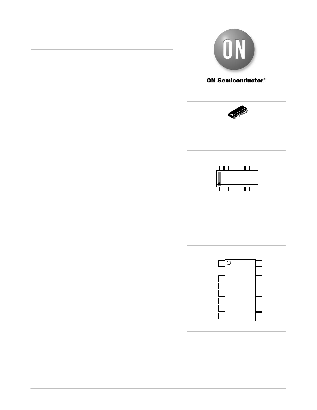
SOIC−16 NB
(LESS PINS 2 AND 13)
D SUFFIX
CASE 751DU
MARKING DIAGRAM
16
NCP1399xy
AWLYWWG
1
NCP1399 = Specific Device Code
x = A or B
y = A, B, C or F
A = Assembly Location
WL = Wafer Lot
Y = Year
WW = Work Week
G = Pb−Free Package
PIN CONNECTIONS
HV 1
VBULK/PFCFB 3
SKIP/REM 4
LLCFB 5
LLCCS 6
OVP/OTP 7
PON/OFF 8
16 VBOOT
15 HB
14 MUPPER
12 MLOWER
11 GND
10 VCC
9 PFCMODE
(Top View)
ORDERING INFORMATION
See detailed ordering and shipping information in the package
dimensions section on page 10 of this data sheet.
© Semiconductor Components Industries, LLC, 2016
February, 2016 − Rev. 4
1
Publication Order Number:
NCP1399/D
1 page 
NCP1399AA, NCP1399BA, NCP1399AC, NCP1399AF
ELECTRICAL CHARACTERISTICS
(For typical values TJ = 25°C, for min/max values TJ = −40°C to +125°C, VCC = 12 V unless otherwise noted.)
Symbol
Rating
Pin Min Typ
HV Startup Current Source
VHV_MIN1
Minimum voltage for current source operation
(VCC = VCC_ON −0.5 V, ISTART2 drops to 95 %)
VHV_MIN2
Minimum voltage for current source operation
(VCC = VCC_ON −0.5 V, ISTART2 drops to 5 mA)
ISTART1
Current flowing out of VCC pin (VCC = 0 V)
ISTART2
Current flowing out of VCC pin (VCC = VCC_ON −0.5 V)
ISTART_OFF
Off−state leakage current (VHV = 500 V, VCC = 15 V)
IHV_OFF−MODE
HV pin current when off−mode operation is active
(VHV = 400 V)
Supply Section
VCC_ON
Turn−on threshold level, VCC going up
VCC_OFF
Minimum operating voltage after turn−on
VCC_RESET
VCC level at which the internal logic gets reset
VCC_INHIBIT
VCC level for ISTART1 to ISTART2 transition
VCC_ON_BLANK Delay to generate DRVs pulses after VCC_ON is reached
ICC_OFF−MODE
Controller supply current in off−mode,
VCC = VCC_ON − 0.2 V
ICC_SKIP−MODE
Controller supply current in skip−mode, VCC = 15 V
ICC_LATCH
Controller supply current in latch−off mode,
VCC = VCC_ON − 0.2 V
ICC_AUTOREC
Controller supply current in auto−recovery mode,
VCC = VCC_ON − 0.2 V
ICC_OPERATION
Controller supply current in normal operation,
fsw = 100 kHz, Cload = 1 nF, VCC = 15 V
Bootstrap Section
VBOOT_ON
Startup voltage on the floating section (Note 5)
VBOOT_OFF
Cutoff voltage on the floating section
IBOOT1
Upper driver consumption, no DRV pulses
IBOOT2
Upper driver consumption, Cload = 1 nF between Pins 13 &
15 fsw = 100 kHz, HB connected to GND
HB Discharger
IDISCHARGE1
HB sink current capability VHB = 30 V
IDISCHARGE2
HB sink current capability VHB = VHB_MIN
VHB_MIN
HB voltage @ IDISCHARGE changes from 2 to 0 mA
Remote Input – NCP1399By
VREM_ON
Remote pin voltage below which off−mode is deactivated
(VREM going down)
VREM_OFF
Remote pin voltage above which off−mode is activated
(VREM going up)
tREM_TIMER
IREM_LEAK
Remote timer duration
Remote input leakage current (VREM = 10 V)
RSW_REM
Internal remote pull down switch resistance (VREM = 8 V)
2. The NCP1399Ay version has skip adjustable externally.
3. Guaranteed by design.
4. Minimal impedance on P ON/OFF pin is 1 kW
5. Minimal resistance connected in series with bootstrap diode is 3.3 W
1
1
1, 10
1, 10
1
1
10
10
10
10
10
10, 11
10, 11
10, 11
10, 11
10, 11
16, 15
16, 15
16, 15
16, 15
15
15
15
4
4
4
4
4
−−
−−
0.2 0.5
69
−−
−−
15.3 15.8
9.0 9.5
5.8 6.6
0.40 0.80
100 125
10 27
580 750
330 490
300 490
4.0 5.4
89
7.2 8.2
30 75
1.30 1.65
5−
1−
−−
1.0 1.5
7.2 8.0
80 100
− 0.02
3−
Max
60
60
0.8
13
10
8
16.3
10
7.2
1.25
150
40
900
600
600
7.0
10
9.0
130
2.00
−
−
10
2.0
8.8
120
1.00
7
Unit
V
V
mA
mA
mA
mA
V
V
V
V
ms
mA
mA
mA
mA
mA
V
V
mA
mA
mA
mA
V
V
V
ms
mA
kW
www.onsemi.com
5
5 Page 
NCP1399AA, NCP1399BA, NCP1399AC, NCP1399AF
TYPICAL CHARACTERISTICS
0.30 1.05
0.25 0.95
0.20 0.85
0.15 0.75
0.10 0.65
0.05 0.55
0 0.45
−55 −25 5 35 65 95 125
−55 −25 5 35 65 95 125
TEMPERATURE (°C)
TEMPERATURE (°C)
Figure 5. ISTART_OFF vs. Temperature
Figure 6. VCC_INHIBIT vs. Temperature
0.55
0.54
0.53
0.52
0.51
0.50
−55
−25 5 35 65 95
TEMPERATURE (°C)
Figure 7. ISTART1 vs. Temperature
125
9.4
9.3
9.2
9.1
9.0
8.9
8.8
8.7
8.6
−55
−25 5 35 65 95
TEMPERATURE (°C)
Figure 8. ISTART2 vs. Temperature
125
9.45 15.85
9.43 15.80
9.41 15.75
9.39 15.70
9.37
−55
−25 5 35 65 95
TEMPERATURE (°C)
Figure 9. VCC_OFF vs. Temperature
15.65
125 −55 −25 5 35 65 95
TEMPERATURE (°C)
Figure 10. VCC_ON vs. Temperature
125
www.onsemi.com
11
11 Page | ||
| Páginas | Total 30 Páginas | |
| PDF Descargar | [ Datasheet NCP1399AC.PDF ] | |
Hoja de datos destacado
| Número de pieza | Descripción | Fabricantes |
| NCP1399AA | High Performance Current Mode Resonant Controller | ON Semiconductor |
| NCP1399AC | High Performance Current Mode Resonant Controller | ON Semiconductor |
| NCP1399AF | High Performance Current Mode Resonant Controller | ON Semiconductor |
| Número de pieza | Descripción | Fabricantes |
| SLA6805M | High Voltage 3 phase Motor Driver IC. |
Sanken |
| SDC1742 | 12- and 14-Bit Hybrid Synchro / Resolver-to-Digital Converters. |
Analog Devices |
|
DataSheet.es es una pagina web que funciona como un repositorio de manuales o hoja de datos de muchos de los productos más populares, |
| DataSheet.es | 2020 | Privacy Policy | Contacto | Buscar |